About the Product
Installation and Removal
21 9831/0650-3 21
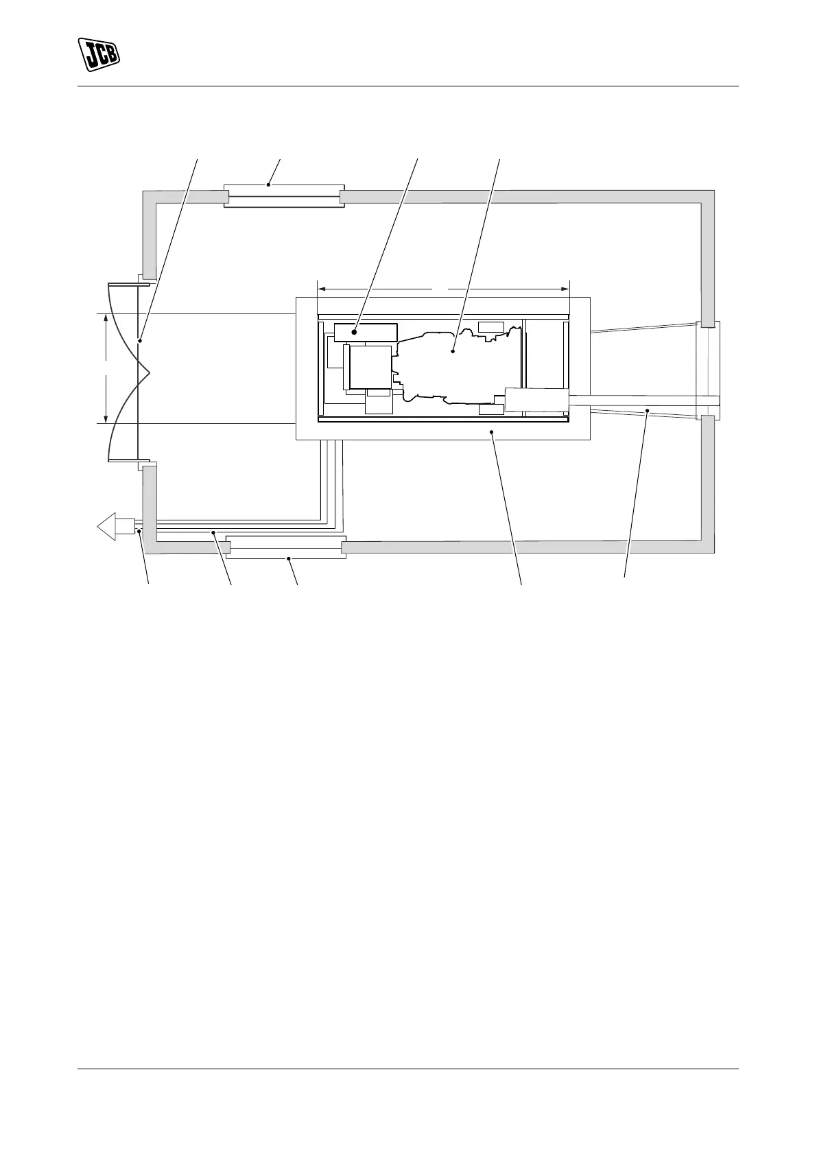
Figure 15. Open Generator Set - Plan View
A Access door B Air inlet grille
C Control panel D Generator set
E Hot air outlet duct F Concrete base
G Cable conduit H Cable exit
J Generator length + 200mm K Generator width + 200mm
Basic Elements to be Considered
• Foundations
• Exhaust installations
• Ventilation
• Fuel installation
• Electrical connections
• Grounding
• Heating
Foundations
Foundations must prevent the transmission of vibrations and noise to other parts of the building.
The surface on which the set will be placed must be levelled in order to allow its correct operation.
Exhaust Installation
The pipes must evacuate the gases to those areas where they cause no danger or damage, and must end
with a protection cap to protect them from water entry.
The connection between the engine's manifold (or the turbocharger) and the pipe must be made a section of
flexible tube, to absorb thermal expansion and vibration.