Maintenance
Engine
96 9831/0650-3 96
• Parameters: Volt, Stab, Amp and Hz can be set with trimmers (default) 50/60Hz through a jumper (default).
All parameters can be programmed via software
• Analogical remote control of output voltage is possible through external voltage (0 to 2, 5V DC) or with
a 10 kohm linear potentiometer
• Environmental temperature: - -25°C (-13.0°F) to 70°C (157.9°F)
• Underspeed protection with adjustable threshold and slope
• Overvoltage and undervoltage alarms
• Excitation overcurrent protection with delayed intervention
• Management of temporary short circuits (start up of asynchronous motors)
• Open collector output (not insulated) signalling intervention of protective devices (insulation on optional
DI1 module) with programmable activation with respect to the individual alarms and the possibility to delay
intervention
• Abnormal operation conditions storage (type of alarm, number of events, duration of the last event, total
time)
• Memorization of the regulator operation time (starting from revision 11 of the Firmware)
• RS232 and RS485 serial communications interface (with optional DI1 module).
Operation of the DSR is not specified below 12Hz.
Installation
Upon receipt of the digital regulator, perform a visual inspection to ensure that no damage has been sustained
during transportation and movement of the equipment.
In the event of damage, advise the shipper, the insurance company, the seller or Mecc Alte immediately. If the
regulator is not installed immediately, store it in its original packaging in a dust and humidity-free environment.
The regulator is normally installed in the generator terminal box. It is fixed with two M4x20 or M4x25 screws and
must be installed in a location where the temperature does not exceed the environmental conditions foreseen.
Connection
The digital regulator connections depend on the application and excitation system for the functional aspect of
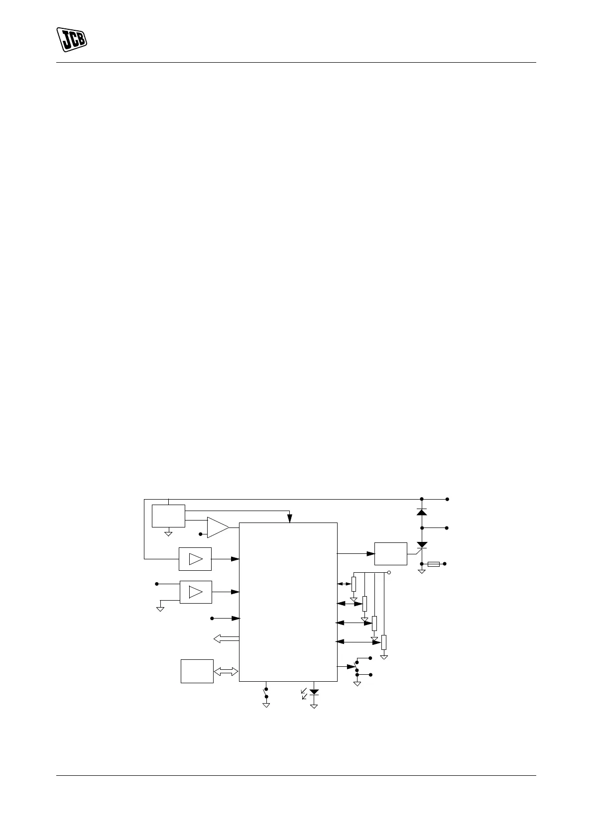
the connection points to the regulator. Refer to Figure 75.
Figure 75. Block Diagram
A DSP B Aux. Exc+
C Exc- D Driver
E Auxiliary F Ground
G Volt H Stab
J Ampere K Frequency