Attachments
Working with Attachments
67 9831/0650-3 67
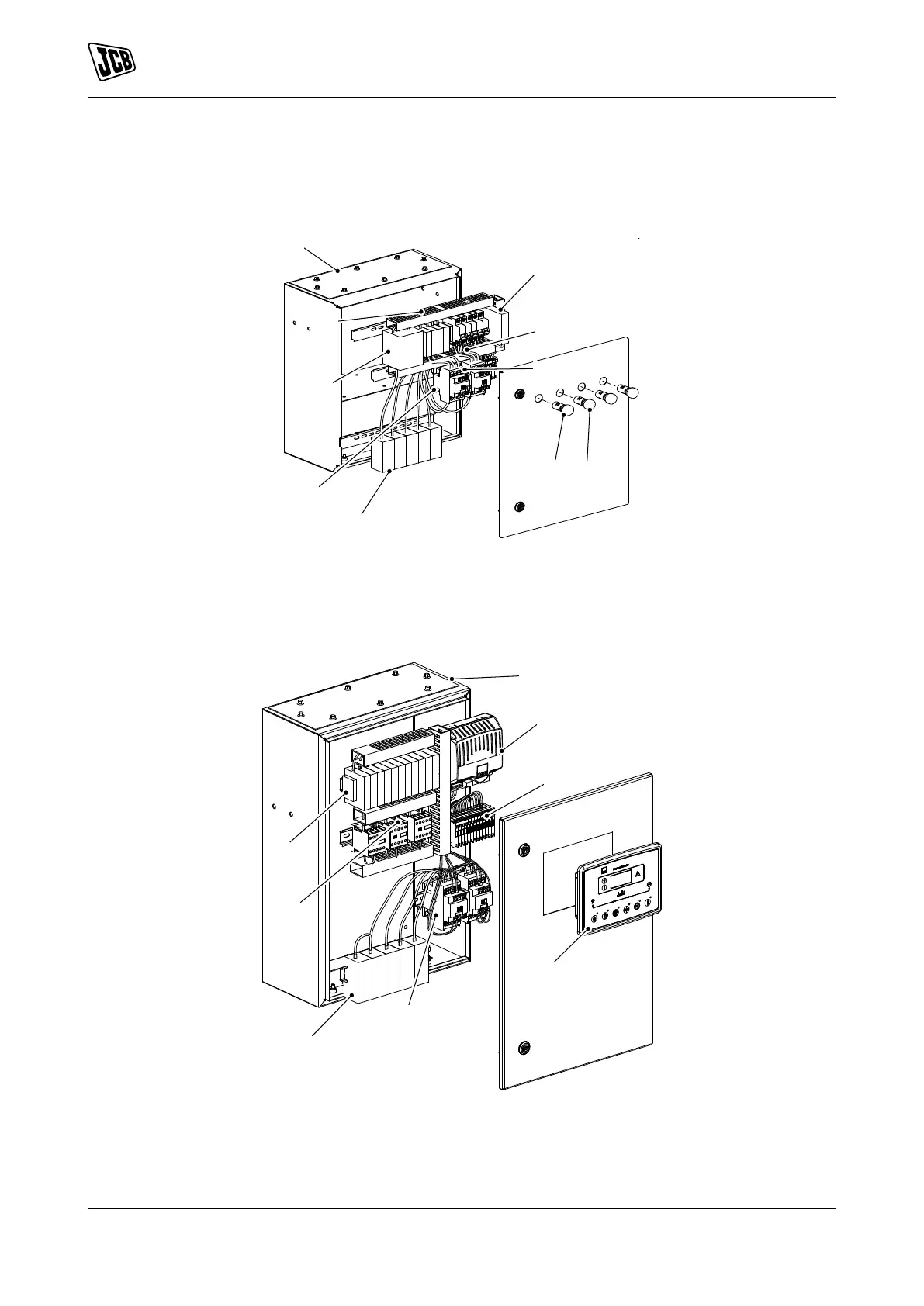
ATP Panel
ATP panel installation differ according to ampere requirements.
Figure 56.
A Control panel box B Monitoring relay
C MCB stopper D Mechanical Interlock
E Indicator LED (yellow) F Indicator LED (red)
G Power busbar terminal H AC contactor
J Voltage surge suppressor K PVC duct
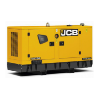
Figure 57.
A Control panel box B Self seeking power supply
C Terminal block D Controller
E AC contactor F Power busbar terminal
G Control relay H MCB stopper