8 Please consult your manual for full information or consult your local dealer.
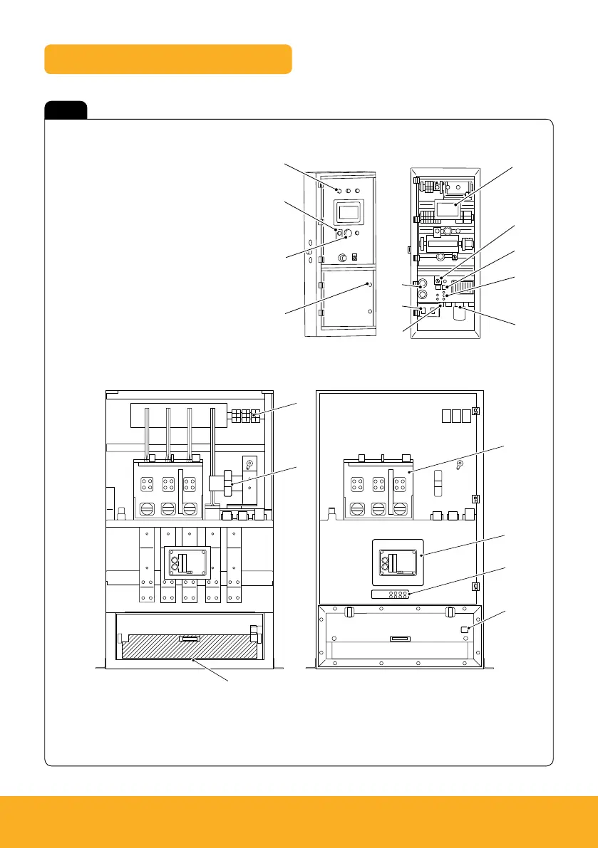
Key components – control panel
A DIN rail terminal
B Toroid
C Self latching cable cover with padlock
D Automatic circuit breaker
E AVR (Alternator Voltage Regulator)
F Test point
A Auxiliary indicator lamps
B Audible alarm
C Hour meter
D Lockable door
E Coolant heater and battery charger sockets
F GFCI 120V Small power
G USB (Universal Serial Bus) port
H Voltage alarm
J End of line synch switches
K Digital synch connections
L Analogue load share connection point
M 3x50A Shore power – 120V/240V
Fig 4
D
B
C
H
J
K
L
M
G
F
E
G
C
F
E
B
D
A