Moving the bender
In order to save you money, the bender is sold without the
moving handles. Why? The 5 1/2 foot long handles will not t into
the bender’s crate and therefore must be shipped separately at
an average cost of over $40. The handle material itself however
is less than $10.
Installing the handles
Obtain 2 pieces of 1” pipe or 1 1/4” tubing at least 5 1/2 feet
long. Insert both handles into the 2 outer holes as shown to the
right and push them past the 2 inner holes until they bottom out.
Now you can easily move the bender around.
Floor mount or wheeled?
In order to achieve best results, the spindle must always be
as level as possible. To illustrate the problem, let’s assume the
bender is wheeled into position but the oor is 1
o
off level from the horizon. The operator makes a 90
o
bend.
Now the operator repositions the tube for the second bend and carefully levels the tube to the horizon and makes
the second bend. This repeats for a third bend. The result will be the rst and the last bend are now 2
o
off plane
from each other. We refer to this as cork screwing. Therefore, the best way to setup up the bender is to mount it
directly to the oor as described later.
Wheeled installation
While oor mounting is denitely the best way to go sometimes the bender must be mobile. In this case, locate
the 1/2” bolts, nuts and washers you removed when uncrating the machine. Refering to the photo above, install
them back into the same holes in the base from where you previously removed them. The head of the bolt must
face down. The two bolts can now be used to level the bender.
Floor mounted installation
Remove the front wheels. Using the holes in the stand or the measurements below, mark the oor at the 4
corners of the bender’s stand. Now drill the holes and cement 1/2” threaded rods into the oor. Using 3 pairs of
nuts and washers at each corner, level the spindle’s top as described in the next section. Because the stand’s
welded dimensions may vary slightly from the drawing, verify the holes in the oor match the one’s in the bender
before cementing in the threaded rods.
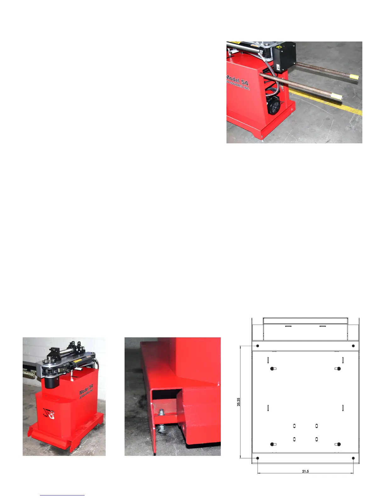
Assembly
Bender shown with handles and the two rear
leveling bolts installed.
Page 4
Front corner, wheel removedBender mounted to oor
25.25
21.5
FRONT