STARTING
UP
AND GENERAL RUNNING HINTS
Treat the new car with consideration. Although every JENSEN car
is thoroughly tested on the road, the first few hundred miles should be done at a
moderate speed. We do not tie
JENSEN
owners to the monotonous observance
of an arbitrary maximum speed for a given distance, but we recommend that sus-
tained high speeds in excess of say
60
miles per hour be avoided until the car has had
reasonable time to settle down and all moving parts are freed from their
initial stiffness. The observance of these precautions will be reflected later on in
the prolonged life of the car. Under this heading, lubrication
is
by far the most
important item. Many troubles are directly traceable to lack of proper lubrication
and owners will be well repaid by giving careful attention to the lubrication diagram
Page
11.
The engine attains maximum power at
3700
r.p.m. and
4000
r.p.m. should not
be exceeded.
We strongly recommend owners who do not wish to carry out their own oiling
and greasing to take advantage, where possible, of the facilities offered by service
stations with modern lubrication equipment.
The illustration on page four shows the general arrangement of controls and
the following points should be observed in starting the engine.
(a) Ensure that the gear control lever is in neutral.
(b) Switch on the ignition and
if
starting from cold, pull out switch on facia
marked
C.
This operates a small electric starting carburetter which feeds
a rich mixture to all the cylinders. Press starting switch firmly.
The engine
should then start immediately.
Never Race the Engine from a cold
start-this
is
most injurious.
The starting carburetter must be switched off when the engine has warmed
up. As a general guide, this will take place after
+
to
74
miles have been
covered, depending on the ambient temperature.
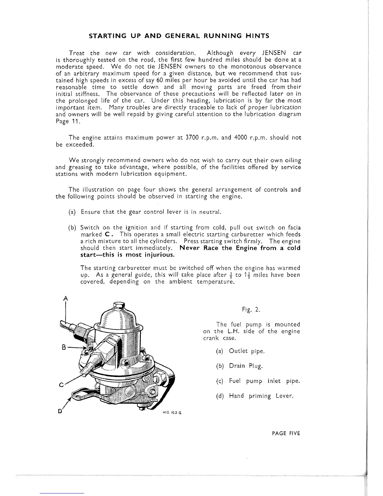
Fig.
2.
The fuel pump is mounted
on the
L.H.
side of the engine
crank case.
(a) Outlet pipe.
(b) Drain Plug.
(c) Fuel pump inlet pipe.
(d) Hand priming Lever.
PAGE
FIVE
 Loading...