Name:
Nr.:
1
1
2
3
4
5
6
7
8
9
10
11
12
2 11-10
9-101-2
3-2
5-6
7-6
1-2
3-2
3-2
3-2
1-2
1-2
27-10
5-2
5-2
5-2
7-2
7-2
7-2
15-6
9-6
9-6
9-6
13-6
13-6
13-6
11-6
11-6
11-6
17-6
17-6
25-10
25-10
19-10
19-10
19-10
23-10
23-10
23-10
21-10
21-10
21-10
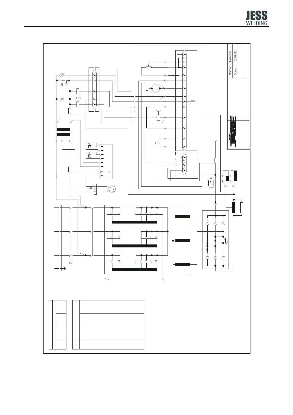
400V 3~50Hz
Schweiß- und
Schneidtechnik
PE L1 L2 L3
Q1
1 3 5
642
1 3 5
2 4 6
K1
Q2
3
1
27
6 2 10
2 1
4
6
8
5 910
12
17
13
11
9
15
7
5
21
23
19
25
T1
F1
T2
400 V
230 V
0 V
42 V
0 V
F2
Y2
H2
4b
1210 11
3b2b1b
9
8a
8a
8
7a
7a
7
6a
6a
6
5a
5
4a
4a
4
5a
3a
3a
3
2a
1a
21
2a
4b 6b5b
M
T 6,3 AF2
1a1 2 3 4 5 6
+
35 4 2 1
S1
5 4 3 2 1
Y1
3b1b 2b
Tuchel 5 pol.
V1
L1
R2
-
1µF
M
1
blue
brown
black
M2
109876531
VR 1
S8 S9
H1
T 6,3 A
T 2 A
S6
S7
K1
A2
A1
M1
R3
S3S3S3S3
+
-
440.032.107
440.032.106
440.020.044
Q3
Gerlach
R1
Date: 12.09.00
MIG-326.023
The bridges 3b-5b and 2b-6b
must be removed if an ext.
wire feed poti is connected.
wire feed unit
control box MS9/MS14/MSE
MSE 2
workpiece
torch
luster-
terminal
luster-
terminal
luster-
terminal
fan
transition
hose-pack
A1 fan control
p.c.b. since
13.01.97
grade contacts
contacts
Q2 weld grade switch, coarseQ2
weld grade switch, fineQ3
grade
H1
M2
M1
L1
K1
H2
C1
F1,F2
condensator 1µF/400V
fuse aux. transformer
mains control lamp
malfunction lamp temp.
mains contactor
choke
wire feed motor 42V
fan
R3
R1
R2
Q1
Q2
Q3
master switch
weld grade sw. coar.
weld grade sw. fine
wire feed poti ext.
resistor
resistor shunt
S1 torch trigger
S3 reed switch (creep-in)
S6
S7 thermoswitch transf. 170°C
thermoswitch tect. 80° C
S8
S9S9
thermoswitch rect. 50° C
thermoswitch transf. 80° C
T1
T2
welding transformer
aux. transformer
Y1
Y2
V1 rectifier
solenoid valve
solenoid valve
Circuit Diagram
MIG 326