1. All dimensions shown for the framing trim out and metal heat shields, are based on a maximum frontal clearance
between the timber framing and the rear of the firebox fascia, being not more than 15mm.
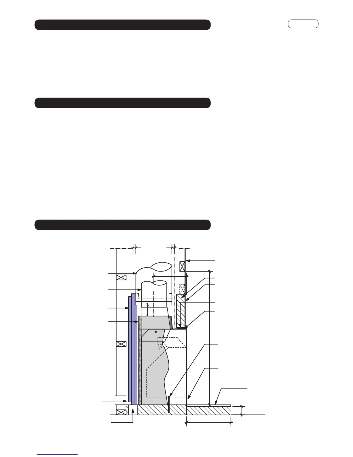
2. Locate floor protector in trim out cavity. If on a concrete floor, suggest a mortar screed to the underside of the floor
protector. If on a wooden floor, screw or dynabolt in place.
3. Locate stud openings on both sides.
4. Position and ensure a strip of glass rock wool insulation is between the inner hebel leg face and the firebox. Nail
through stud into hebel leg to secure in place.
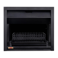
5. Locate and position firebox, fit and seal gather in cavity (refer to Cross Section). Earthquake restraints may be
positioned by drilling through firebox into the floor protector, in a position midway beneath the log-pan. Two 12mm
dynabolts or similar will suffice. Do not over tighten and deform firebox.
6. Attach rock wool to the sides & back of the firebox and gather. DO NOT BLOCK OFF the air entry between the inner
flue pipe and flue pipe casing or the air circulation between the vent holes in the cavity.
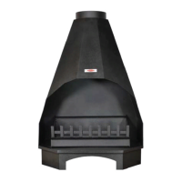
7. Once the flue system is installed, place a minimum 300mm hebel block over the top of the firebox (see Fig. 8).
Ensure the hebel block does not rest on top of the firebox. A Lintel Bar may be required.
100
Y
min
75
25
25
B
Refer to the minimum framing dimensions as per table 2. Allow a temporary lintel height (see table 2 ‘B’) from the
finished floor protector level until the firebox and flue system is installed. Install front nogs on edge to increase chimney
chase dimension.
Ensure suitable air vents (2 x 80mm diameter or equivalent) in place to vent firebox space - these maybe located in the
floor or in the side wall space. Ensure vents must be bird and vermin proofed.
Note: Wood Installations can be converted to Gas at a later date. or have a gas ignition system fitted. Consider running
a gas supply to firebox cavity at the time of construction.
Fig.8
Flue Pipe Casing
S/S Flue Pipe
Heat Shield
Rock Wool
Insulation
min 25mm from flue pipe casing to combustible material
Note: All external air vents
& ceiling penetrations must
be bird & rodent proofed
with permanently fixed
screens
Gib Board
Hebel Block
Non combustible material
(Promina, Eterpan LD, Supalux)
Lintel Bar
Rock Wool insulation
(see Table 2)
Secure the firebox with 2 x
12mm Dynabolts in a midway
position beneath the log pan
Maintain the air intake
unobstructed
Rebate to suit tiles or other non com-
bustible material on Floor Protector
Floor Protector
see Table 4
It is important to ensure the Jetmaster firebox is seated at the
required finished Floor Protector level
min 2 x 80mm dia
or equal square or
rectangle shaped air
vents to be wall or
floor mounted
Drawing Not To Scale
CROSS SECTION
FIREBOX INSTALLATION
CAVITY / FRAMING PREPARATION
5.TW.1D
 Loading...