Solar Controller-SCM48100 User Manual
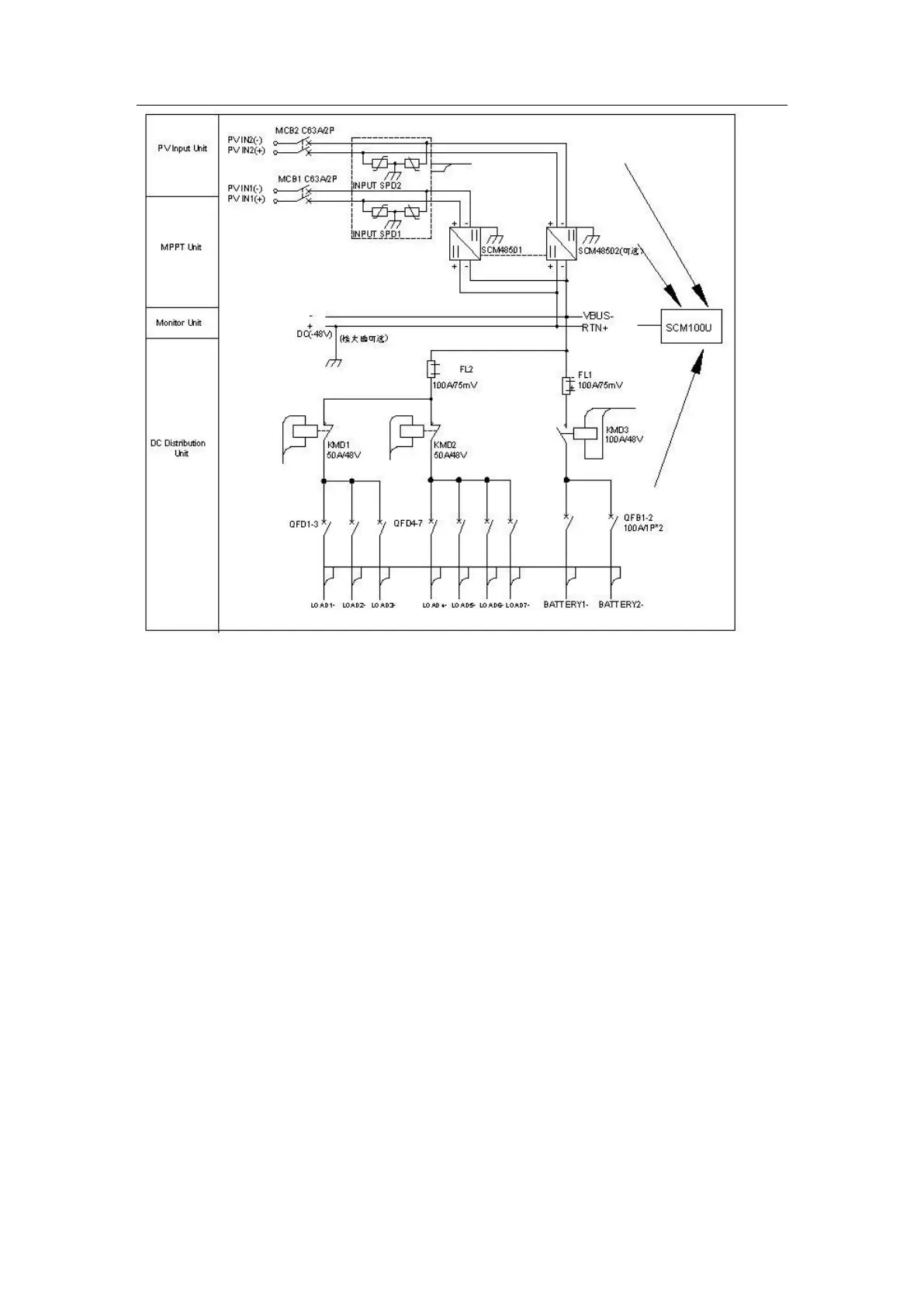
As shown in the diagram above: 2 channels of sub-array input are directly output to
RTN+ and VBUS- bus bar via circuit breaker protection, surge protection and MPPT
module conversion.
The cathodes of 2 channels of battery are connected to BATTERY1- and BATTERY2-
input interfaces respectively. They gather together through two 100A circuit breakers.
Then, they are connected to VBUS- bus bar via battery power-off DC contactor
(100A/48V) and battery shunt (100A/75mA); the anodes of 2 channels of battery are
directly connected to RTN+ bus bar. Single group of battery access port has reverse
connection protection function.
After cathode of backup DC power supply is connected to DC- input interface, it is
directly connected to VBUS- bus bar (M6 self-clinching nut); backup power supply DC+
is directly connected to RTN+ bus bar (M6 self-clinching nut).
One terminal of load shunt (100A/75mV) is directly connected to VBUS- bus bar, while
the other terminal is connected to secondary load normally closed DC contactor KMD1.
The other terminal of the contactor is connected to “Secondary Load” air switch
(LOAD1~3) and provides 3 channels of “Secondary Load” user shunt; meanwhile, the
other terminal of load shunt is connected to secondary load normally closed DC
contactor KMD2. The other terminal of the contactor is connected to “Primary Load” air
switch (LOAD4~7) and provides 4 channels of user shunt. The anodes of 7 channels of