EasyManua.ls Logo

JGINYUE H97M-VHPLUS - User Manual

JGINYUE H97M-VHPLUS
15 pages
Print Icon
To Next Page IconTo Next Page
Loading...
H97M-VH PLUS
User Manual
http://www.jginyue.com/
Question and Answer IconNeed help?

Do you have a question about the JGINYUE H97M-VHPLUS and is the answer not in the manual?

Summary

Overview of Components

Install CPU & Fan

Install Memory

Install Expansion Card

Back Panel Connectors

USB 2.0 Port

Describes the USB 2.0 port functionality for USB devices.

VGA Port

Describes the VGA port for analog video signal transmission.

HDMI Port

Supports 4K and 1080p, for HDMI-supported monitors.

USB 3.0 Port

Supports USB 3.0 and USB 2.0 specifications for USB devices.

RJ45 LAN Port

Gigabit Ethernet port for internet connection up to 1000Mbps/s.

Audio Port

Includes Line-in, Line-out, and Mic-in jacks for audio input/output.

PS;2 Port

Ports for green mouse and blue keyboard.

Internal Connectors

F_PANEL1 Connector

Connects front panel power switch, LEDs, and reset switch.

SPEAK1 Connector

Connector for buzzer and speaker on the front panel.

JAUDIO1 Connector

Connects front panel audio jacks (MIC, headphone).

JCOM1: Serial Port Connector

Provides a serial port via an optional COM port cable.

SATA1~4: SATA 3.0 Connectors

Four SATA 6Gb/s interface ports for connecting SATA devices.

SATA M.2 Slot

Slot for installing an M.2 SSD at a 30-degree angle.

WLAN-1 Slot

M.2 WiFi interface compatible with WiFi AC expansion cards.

JCMOS1: CMOS Discharge

Jumper for clearing CMOS settings to reset BIOS to defaults.

ATXPWR1, JATXPWR1: Power Connectors

CPU_FAN1, SYS_FAN1: Fan Connectors

JUSB2~3: USB 2.0 Connectors

FUSB3: USB 3.0 Connector

BIOS Setup

Enter BIOS Setup

Reset BIOS

Overview

This document serves as a user manual for the H97M-VH PLUS motherboard, providing comprehensive instructions for its installation, configuration, and maintenance. The manual is designed to guide users through the process of setting up their computer system, from installing core components like the CPU and memory to connecting various peripherals and configuring the BIOS.

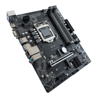
The motherboard is a central component of any computer system, acting as the main circuit board that connects and allows communication between all other hardware components. Its primary function is to provide the electrical connections and communication pathways for the CPU, RAM, storage devices, expansion cards, and external peripherals. The H97M-VH PLUS is designed to support a range of Intel processors, specifically the Core i7/i5/i3 Celeron/Pentium/E3 LGA1150 pin series, making it suitable for a variety of computing needs, from general office use to more demanding tasks.

Installation and Setup

The manual begins with a critical section on installing the CPU and its fan. This process requires careful attention to detail to prevent damage to the delicate pins of the CPU socket. Users are instructed to align the CPU correctly with the LGA 1150 socket, ensuring that the locking lever is lifted before insertion and then secured afterward. A crucial maintenance tip provided here is to apply an even layer of thermal paste between the CPU and the heatsink to enhance heat dissipation, which is vital for preventing overheating and ensuring the longevity of the processor. The importance of installing the CPU cooler before powering on the system is also emphasized, as running the CPU without proper cooling can lead to immediate damage.

Following the CPU installation, the manual details the process of installing memory modules. The H97M-VH PLUS motherboard features four DDR3 DIMM slots, supporting a maximum capacity of 32GB. Users are guided to wrench the latches outwards, align the memory module with the notch in the slot, and then flip the latches back to secure it. A key usage feature highlighted is the motherboard's support for Dual Channel Technology, which can enhance memory performance. However, it's noted that Dual-Channel mode requires at least two memory modules to be installed. Maintenance advice includes ensuring that the motherboard supports the specific memory modules being used and, ideally, using memory of the same capacity, brand, speed, and chips for optimal stability. The foolproof design of memory modules, allowing insertion in only one direction, is also mentioned as a helpful feature to prevent incorrect installation.

The installation of expansion cards, such as graphics cards or other PCI Express devices, is also covered. The motherboard provides a PCI Express 3.0 x16 slot and a PCI Express 2.0 x1 slot. Users are instructed to firmly insert the expansion card into an available slot. A critical maintenance warning is given: always turn off the power supply and unplug the power cable before adding or removing expansion cards to prevent hardware damage and short circuits.

Connectivity

The manual then moves on to describe the various connectors available on the H97M-VH PLUS motherboard, both on the back panel and internally.

Back Panel Connectors: These are the ports visible on the rear of the computer case, allowing for easy connection of external peripherals.

  • USB 2.0 and USB 3.0 Ports: The motherboard includes both USB 2.0 and USB 3.0 ports. USB 3.0 offers significantly faster data transfer rates and is backward compatible with USB 2.0 devices. These ports are essential for connecting a wide range of peripherals, including keyboards, mice, external hard drives, and printers.
  • VGA Port: This port supports analog video signal transmission, offering high resolution and rich colors, typically used for connecting monitors.
  • HDMI Port: A modern video output, the HDMI port supports 4K and 1080px resolutions, allowing connection to high-definition displays and TVs.
  • RJ45 LAN Port: This Gigabit Ethernet LAN port provides internet connectivity at speeds up to 1000Mbps/s. The manual includes a useful feature: a description of the LAN port's LED indicators (Link/Activity and Speed LEDs), which help users quickly diagnose network connection status.
  • Audio Ports: The motherboard features standard audio jacks, including Line-in (for devices like optical drives or walkmans), Line-out (for speakers or headphones), and Mic-in (for microphones).
  • PS/2 Ports: Dedicated PS/2 ports are provided for connecting a PS/2 keyboard (blue) and mouse (green), catering to users who prefer these traditional input devices.

Internal Connectors: These connectors are located on the motherboard itself and are used to connect internal components or front-panel ports of the computer case.

  • F_PANEL1 Connector: This header is for connecting the front panel's power LED, power switch, HDD LED, and reset switch. Proper connection here is crucial for the basic operation of the computer case's controls.
  • SPEAK1 Connector: This connector is for the internal speaker (buzzer), which provides audible POST codes and system alerts.
  • JAUDIO1 Connector: This header allows connection of the front panel audio jacks, providing convenient access to headphone and microphone ports. A critical maintenance note warns against incorrect connections, which can damage the device or prevent it from working.
  • JCOM1: Serial Port Connector: This connector provides a serial port via an optional COM port cable, useful for connecting older peripherals or for specific industrial applications.
  • SATA1~4: SATA 3.0 Connectors: These four connectors support SATA 6Gb/s interface ports, used for connecting storage devices like hard drives and SSDs.
  • SATA M.2 Slot: The motherboard includes an M.2 slot for high-speed M.2 SSDs. The installation process involves inserting the SSD at a 30-degree angle and securing it with a screw.
  • WLAN-1 Slot: This M.2 WiFi interface is compatible with WiFi AC standard expansion cards, allowing users to add wireless connectivity to their system after installing the module and its corresponding driver.
  • JCMOS1: CMOS Discharge: This jumper is a crucial maintenance feature. It allows users to clear the CMOS memory, which stores BIOS settings. This is often necessary to reset BIOS settings to default in case of configuration issues. The manual provides clear steps for discharging and restoring the CMOS, emphasizing the importance of turning off and unplugging the computer before performing this action.
  • ATXPWR1, JATXPWR1: Power Connectors: These connectors are for the main power supply unit (PSU). The ATXPWR1 is the 24-pin main power connector, and JATXPWR1 is the 8-pin CPU power connector. Proper connection ensures stable power delivery to all motherboard components. A significant maintenance recommendation is to use a power supply unit that can withstand high power consumption (at least 500W) to prevent system instability or boot failures.
  • CPU_FAN1, SYS_FAN1: Fan Connectors: CPU_FAN1 is a 4-pin header for the CPU radiator fan, featuring PWM intelligent speed regulation based on CPU load and temperature. SYS_FAN1 is a 3-pin header for a system cooling fan, typically connected to a case fan, but without PWM adjustment capability. These connectors are essential for maintaining optimal system temperatures.
  • JUSB2~3: USB 2.0 Connectors: These headers allow connection of additional USB 2.0 ports, typically found on the front panel of the computer case.
  • FUSB3: USB 3.0 Connector: This header supports USB 3.0 and USB 2.0 specifications, enabling the connection of front panel USB 3.0 ports for faster data transfer.

BIOS Setup

The final section of the manual focuses on the BIOS (Basic Input and Output System). The BIOS is firmware that initializes and tests hardware components during startup and loads the operating system. It also allows users to modify basic system configuration settings.

Entering BIOS Setup: Users can access the BIOS setup menu by pressing the key during the computer's self-test process (POST). If the message disappears too quickly, users can restart the computer or press ++.

Resetting BIOS: The manual provides methods for resetting BIOS settings to their default values, which is a common troubleshooting step. Users can press F6 within the BIOS to load optimized defaults or short the Clear CMOS jumper (JCMOS1) on the motherboard. A critical maintenance warning reiterates the need to turn off the computer before clearing CMOS data.

Maintenance Features and Important Notes: Throughout the manual, several important notes and maintenance features are highlighted:

  • Power Disconnection: A recurring theme is the necessity to always unplug the power cord from the outlet before installing or removing any components to prevent hardware damage.
  • CPU Protection: Retaining the CPU protective cap after installation and covering the socket with a plastic cap when the CPU is not installed are crucial for protecting the CPU socket pins.
  • Thermal Paste: Applying thermal paste for CPU cooling is emphasized for optimal heat dissipation.
  • Component Compatibility: Users are advised to ensure that the motherboard supports the specific CPU and memory modules being installed.
  • Memory Installation: The foolproof design of memory modules and the requirement for two modules for Dual-Channel mode are practical usage features.
  • Power Supply Capacity: The recommendation for a robust power supply (at least 500W) is a key maintenance tip for system stability.
  • BIOS Flashing Caution: Users are warned about the risks associated with BIOS flashing and advised against it unless absolutely necessary, as inadequate flashing can lead to system malfunction.
  • BIOS Settings: The default BIOS settings are presented as optimal for system stability, and users are cautioned against altering them unless they understand the implications, as incorrect settings can prevent the system from booting.
  • BIOS Updates: It's noted that BIOS items are regularly updated, meaning the descriptions in the manual might slightly differ from the latest BIOS versions, serving as a reminder that the manual is a reference.

In summary, the H97M-VH PLUS user manual provides essential guidance for assembling and maintaining a computer system based on this motherboard. It emphasizes careful installation procedures, highlights key connectivity options, and offers crucial maintenance tips to ensure system stability and longevity.

JGINYUE H97M-VHPLUS Specifications

General IconGeneral
Form FactorMicro ATX
SocketLGA 1150
ChipsetIntel H97
Memory TypeDDR3
Memory Slots2
Maximum Memory16 GB
Memory StandardDDR3 1600/1333 MHz
PCI Express x161
PCI Express x11
SATA 6Gb/s6
USB 3.04
USB 2.06
Video OutputsVGA, HDMI
LANGigabit LAN

Related product manuals