Do you have a question about the JL Audio JD250/1 and is the answer not in the manual?
Advises users to limit exposure to high sound pressure levels to prevent permanent hearing loss.
Instructions to record the product's serial number for service or theft purposes.
Covers vehicle system compatibility, installation planning, cooling, safety, and common mistakes.
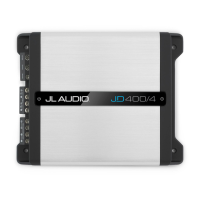
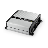
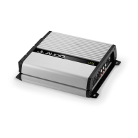
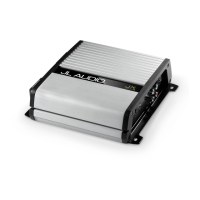
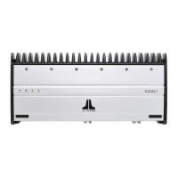
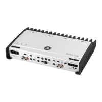
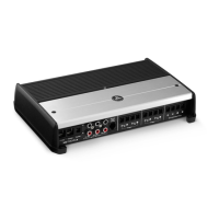
Lists included items and provides a product description of the amplifiers.
Provides a step-by-step guide for installing the amplifier in a vehicle.
Details the procedure for safely connecting the amplifier's power supply wires.
Specifies minimum wire gauge requirements for power and ground connections and important notes on wire types.
Lists the recommended fuse values for each amplifier model and emphasizes proper fuse placement.
Explains the three methods for turning the amplifier on/off: +12V Remote, DC Offset-Sensing, and Signal-Sensing.
Describes the differential-balanced input topology and how to connect stereo or mono signals.
Explains the 'Low' and 'High' input voltage settings for preamp and speaker-level signals.
Details how to use the 'Input Sens.' control and 'Clipping' LED for setting input sensitivity.
Explains the function and operation of the active low-pass filter for subwoofer frequency control.
Covers the Bass Boost equalizer and the optional Remote Level Control (RBC-1).
Details the buffered pass-through preamp outputs for connecting additional amplifiers.
Describes the subwoofer output terminals, their parallel connection, and impedance recommendations.
Explains the meaning of the Status LED and the Protection LED (constant/flashing red).
Discusses conditions causing unexpected shutdowns, primarily low voltage, and suggests inspection.
Provides instructions for returning the amplifier for service, emphasizing authorized service personnel.
Step-by-step guide to properly adjust amplifier input sensitivity for optimal system balance.
Detailed technical specifications for JD250/1, JD500/1, and JD1000/1 models.
Addresses common problems like no turn-on, ticking sounds, and fluctuating output.
Details the warranty period, coverage, exclusions, and service procedures for USA customers.
This document is an owner's manual for JL Audio Class D Monoblock Subwoofer Amplifiers, specifically the JD250/1, JD500/1, and JD1000/1 models. It provides comprehensive information on installation, operation, and troubleshooting to ensure optimal performance and longevity of the amplifier in an automotive sound system.
These JD monoblock amplifiers are designed to power subwoofers in automotive sound systems. They utilize JL Audio's NexD™ high-speed switching technology to deliver high-fidelity audio and efficient power conversion. Optimized for low-frequency amplification, these amplifiers are suitable for a wide variety of source units and system configurations. Their frequency response is limited to below 500 Hz, making them specifically designed for subwoofers and not for driving midrange speakers or tweeters. The amplifiers are equipped with a differential-balanced input topology, which offers high input flexibility and superior noise rejection, allowing them to accept high-voltage inputs from factory source units without distortion or noise. They also feature an active low-pass filter to attenuate frequencies above a selectable cutoff, preventing subwoofers from reproducing audible midrange content and improving tonal balance. A bass boost equalizer is included to enhance low-frequency output.
The manual emphasizes the importance of proper installation, ideally by an authorized JL Audio dealer, to achieve maximum performance. For self-installation, users are advised to thoroughly read the manual to familiarize themselves with installation requirements and setup procedures.
Power Connections: The amplifiers operate on 12V, negative-ground electrical systems. Users must disconnect the negative battery post before installation to prevent damage. Appropriate copper power wire (8 AWG for JD250/1, 4 AWG for JD500/1 and JD1000/1) should be run from the battery to the amplifier, with a fuse installed within 18 inches (45 cm) of the positive battery post. A solid metal grounding point close to the amplifier is required, using the same size power wire as the +12V connection, no longer than 36 inches (90 cm). The manual strongly recommends using oxygen-free copper (OFC) or tinned copper wire for power/ground connections and advises against copper-clad aluminum (CCA) wire. It also highlights the need to upgrade battery ground and alternator wires to 4 AWG if the main fuse rating exceeds 60A to prevent voltage drops.
Turn-On Options: The amplifier can be turned on/off using one of three methods, selected via the "Turn-On Mode" switch:
Input Section: The amplifier's input section automatically sums stereo signals to mono. Users can run stereo or mono signals into the inputs. If only one input connection is used, a Y-adaptor may be necessary to split the signal into both inputs. For automatic turn-on with DC Offset or Signal Sensing modes, the CH. 1 (L) channel input must be used.
Input Voltage Range: A wide range of input voltages (200mV – 8V) is accommodated via the "Input Voltage" switch:
Input Sensitivity Controls: The "Input Sens." control matches the source unit's output voltage to the amplifier's input stage for maximum clean output. Rotating clockwise increases sensitivity, while counter-clockwise decreases it. A "Clipping" LED trim ring simplifies the setting process, indicating maximum unclipped output. The manual provides a detailed seven-step procedure for setting input sensitivity, emphasizing the importance of disconnecting speakers during the process and not exceeding the maximum unclipped level to prevent distortion and speaker damage.
Low-Pass Filter Control: A 12 dB per octave low-pass active filter with a continuously variable frequency selection from 50 Hz to 500 Hz is included. This filter is crucial for preventing subwoofers from reproducing midrange content. 80 Hz is suggested as a good starting point for tuning.
Bass Boost Control: A single-band, boost-only bass equalizer with a rotary knob allows adjustment from 0 dB (full-counterclockwise) to +12 dB (full-clockwise), centered at 45 Hz.
Preouts: Buffered, pass-through preamp outputs are provided, delivering the same signal as the amplifier's inputs, allowing for easy addition of more amplifiers. The preamp output signal is not affected by the amplifier's filter controls. When the "Input Voltage" switch is in "Low," the "Preouts" signal matches the input level (unity gain). In "High" position, the input signal is attenuated by -12 dB to produce a line-level signal at the "Preouts" for proper line-level output. If using "Preouts" to feed a stereo amplifier, a stereo signal must be connected to the amplifier's inputs.
Remote Level Control (Optional): An optional RBC-1 remote level control allows users to adjust subwoofer volume from the front of the vehicle. It connects via a standard telephone cable and acts as a level attenuator, muting audio at full counter-clockwise rotation and providing full level at full clockwise rotation. Multiple JD monoblock amplifiers can be controlled by a single RBC-1 using a phone line splitter.
Subwoofer Outputs: The amplifiers are designed to deliver power into subwoofer loads of 2 ohms or greater. The outputs accept 16 AWG - 8 AWG wire. There are two positive and two negative connections, which are connected in parallel internally, facilitating multiple subwoofer wiring. Connecting two subwoofers to one set of terminals results in a parallel connection.
Cooling Efficiency: The amplifier's outer shell is designed for heat removal. It should be exposed to a large volume of air for optimum cooling. Mounting upside down is discouraged, and at least 1 inch (2.5 cm) of space above the amplifier is recommended for proper cooling if mounted under a seat. Enclosing the amplifier in a small, poorly ventilated chamber can lead to excessive heat build-up and degraded performance; if an enclosure is necessary, fan ventilation is recommended.
Safety Considerations: The amplifier must be installed in a dry, well-ventilated environment and secured to prevent it from coming loose. Installation should not interfere with vehicle safety equipment (air bags, seat belts, ABS brakes). Users are warned against drilling through vital vehicle systems, running wires outside the vehicle, and mounting the amplifier in areas exposed to elements. All wires should be protected from sharp edges.
Status LEDs / Protection Circuitry: The amplifier has Status and Protection LEDs on its top surface.
Troubleshooting: The manual includes a troubleshooting guide for common issues:
Servicing: There are no user-serviceable parts or fuses inside the amplifier. Users are advised to return malfunctioning amplifiers to an authorized JL Audio dealer for service, as unauthorized repair voids the warranty and can cause further problems.
Warranty: JL Audio provides a two-year warranty on the product, extended to three years if installed by an authorized JL Audio dealer using a JL Audio Premium Power Connection System. The warranty covers manufacturing defects and malfunctions but excludes damage from accident, misuse, abuse, modification, neglect, improper installation, unauthorized repair, or misrepresentations. Cosmetic damage and incidental/consequential damages are not covered. The warranty is void if the serial number is removed or defaced. Warranty returns require proof of purchase and must be sent freight-prepaid to JL Audio's Amplifier Service Facility.
| Fuse Rating | 25 A |
|---|---|
| Rated Power (RMS) | 250 Watts x 1 @ 4 ohms |
| Input Range | 200 mV - 6 V |
| Power Output (RMS) | 250W @ 1.5Ω - 4Ω |
| Input Sensitivity | 200 mV - 6 V |