EasyManua.ls Logo

JL Audio m600 User Manual

JL Audio m600
20 pages
To Next Page IconTo Next Page
Page #1 background imageLoading...
Page #1 background image
Thank you for purchasing a JL Audio amplifier for
your marine sound system.
Your amplifier has been designed and manufactured to exacting
standards in order to ensure years of musical enjoyment in your vessel or
vehicle. For maximum performance, we highly recommend that you have
your new amplifier installed by an authorized JL Audio dealer. Your
authorized dealer has the training, expertise and installation equipment
to ensure optimum performance from this product. Should you
decide to install the amplifier yourself, please take the time
to read this manual thoroughly so as to familiarize yourself
with its installation requirements and setup procedures.
If you have any questions regarding the instructions in this
manual or any aspect of your amplifier’s operation, please contact your
authorized JL Audio dealer for assistance. If you need further assistance,
please call the JL Audio Technical Support Department
at (954) 443-1100 during business hours.
OWNER’S MANUAL
600W Marine 6 Channel Amplier
NOT FOR USE IN 12 V SYSTEMS!
Question and Answer IconNeed help?

Do you have a question about the JL Audio m600 and is the answer not in the manual?

JL Audio m600 Specifications

General IconGeneral
BrandJL Audio
Modelm600
CategoryAmplifier
LanguageEnglish

Summary

Introduction and Safety

PROTECT YOUR HEARING!

Warning to protect hearing from high sound pressure levels.

SERIAL NUMBER

Instructions for recording the product's serial number for service or theft.

INSTALLATION APPLICATIONS

Specifies compatible electrical systems (24V, negative-ground) and restrictions.

Installation Planning

Cooling Efficiency Considerations

Guidelines for optimal amplifier cooling and heat dissipation.

Safety Considerations

Requirements for safe installation in dry, well-ventilated environments.

Stupid Mistakes to Avoid

Common installation errors and dangerous practices to prevent.

Product Overview

PRODUCT DESCRIPTION

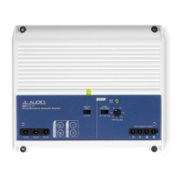
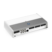
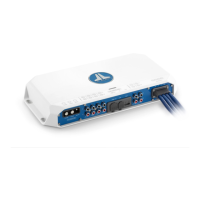
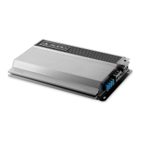
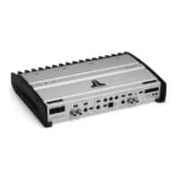
Overview of the JL Audio M600/6-24V amplifier's features and technology.

TYPICAL INSTALLATION SEQUENCE

Step-by-step guide for installing the amplifier in a vessel.

Power and Turn-On Connections

POWER CONNECTIONS

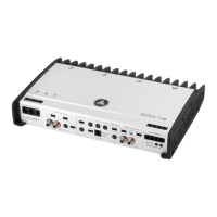
Instructions for connecting the main power wires to the amplifier.

FUSE/CIRCUIT BREAKER REQUIREMENTS

Specifies fuse values and placement for power wire protection.

TURN-ON LEAD

Details on connecting the remote turn-on lead for amplifier activation.

Input and Filtering Controls

INPUT SECTION

Explains how to connect audio signals to the amplifier's input section.

Input Voltage Range

Specifies the acceptable input signal voltage range.

INPUT SENSITIVITY CONTROLS

Guide to adjusting input sensitivity for optimal clean output.

FILTER CONTROLS

Explains how to use the built-in crossover filters (HPF/LPF).

"Filter Mode" Control

Describes the three-position switch for filter selection (Off, LP, HP).

"Filter Freq. (Hz)"

Details on setting the filter's cutoff frequency.

Remote Control and Speaker Outputs

REMOTE LEVEL CONTROL (OPTIONAL)

Information on using the optional remote level control accessory.

"Remote Level Mode" Switch

Explains how to assign the RLC to control specific channel pairs.

SPEAKER OUTPUTS

How to connect speaker wires to the amplifier's output terminals.

BRIDGING CONSIDERATIONS

Explains how to bridge channels for increased power output.

Status, Service, and System Configurations

STATUS LED / PROTECTION CIRCUITRY

Explains the meaning of the amplifier's status LED indicators.

SERVICING YOUR JL AUDIO AMPLIFIER

Instructions for obtaining service and warranty information.

SYSTEM CONFIGURATIONS

Overview of various system configurations the amplifier can support.

BI-AMPLIFIED SYSTEMS

Details on setting up bi-amplified systems with the M600/6-24V.

A) No User Adjustability

Setting up a bi-amp system with one stereo source output.

B) Fade Front vs. Rear with no Subwoofer Level Control

Configuring a system for front-to-rear fade control.

C) Fade Subwoofer Level vs. HF Level

Controlling subwoofer level relative to HF channels.

Advanced System Setup

D) Subwoofer Level Control Only

Configuring for dedicated subwoofer level control.

E) Independent level control of all three channel pairs

Independent level control for all channel pairs.

Crossover Setup for Bi-Amplified System with one M600/6-24V

Specific crossover setup for bi-amplified configurations.

Setup Appendix

APPENDIX A: Input Sensitivity Level Setting

Detailed procedure for setting input sensitivity with a voltmeter.

Necessary Equipment

Lists required equipment for setting input sensitivity.

The Nine-Step Procedure

Step-by-step guide for accurate input sensitivity adjustment.

Specification Appendixes

APPENDIX B: Precise Frequency Selection Chart

Chart for precise selection of filter frequencies.

APPENDIX C: M600/6-24V Specifications

Detailed technical specifications for the M600/6-24V amplifier.

Troubleshooting Guide

"How do I properly set the input sensitivity on my amplifier?"

Addresses setting input sensitivity for optimal performance.

"My amplifier doesn't turn on."

Steps to diagnose and resolve the amplifier not turning on.

"I hear a repetitive ticking or popping sound coming out of the speaker(s)."

Explains causes and solutions for ticking/popping speaker sounds.

"My amplifier shuts off once in a while, usually at higher volumes."

Diagnosing intermittent shut-offs, often volume-related.

"My amplifier turns on, but there is no output."

Steps to troubleshoot and resolve the issue of no audio output.

Warranty Information

LIMITED WARRANTY - AMPLIFIERS (USA)

Details the warranty terms and conditions for the amplifier in the USA.

Related product manuals