Do you have a question about the JLG ES2632 and is the answer not in the manual?
Explains safety alert symbols and signal words like DANGER, WARNING, CAUTION, NOTICE.
Outlines necessary precautions for safe machine usage and maintenance.
Details pre-operation requirements including training, workplace, and machine inspections.
Provides general operating guidelines, safety precautions, and hazard avoidance.
Safety guidelines for towing, lifting, and transporting the machine.
Outlines general safety precautions and hazards during machine maintenance.
Specifies requirements for personnel training and operator responsibilities.
Details essential familiarization points before authorizing an operator.
Covers machine inspections and maintenance requirements.
Lists checks required before each day's operation or operator change.
Guides the operator through a systematic visual inspection of the machine.
Details procedures for verifying the operational status of machine functions.
Provides general information on machine application and operator responsibility.
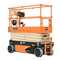
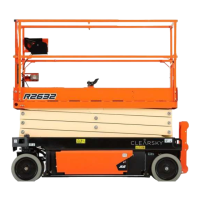
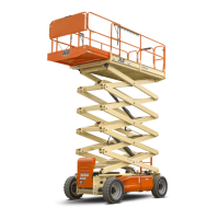
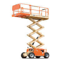
Describes the MEWP and its primary control stations.
Explains operational features, capacities, and stability.
Details platform load capacity and distribution requirements.
Provides instructions and notes for charging the machine's batteries.
Illustrates and identifies the locations of machine control components.
Describes the ground control station and its functions.
Describes the platform control station and its various components.
Illustrates grade and side slope considerations for machine operation.
Details the procedure for extending and retracting the platform deck.
Provides step-by-step instructions for folding down platform rails.
Explains the procedure for manually lowering the platform in case of power failure.
Outlines procedures for safely parking and stowing the machine.
Covers safe methods for lifting and securing the machine for transport.
Provides instructions for towing the machine, including brake release.
Describes the function and types of beacons used on the machine.
Introduces the ClearSky Smart Fleet system for fleet management.
Details access control features that restrict machine functionality.
Shows the placement of safety decals on the machine.
Provides a legend explaining the meaning of safety decals.
Explains steps for emergency situations during operation.
Outlines procedures for notifying JLG Industries about incidents.
Covers procedures for operating the machine in emergency scenarios.
Details manual descent procedure for power failure.
Explains the machine's locked out state and how to address it.
Lists various optional accessories available for the machine.
Describes lockable covers for control stations to prevent unauthorized use.
Explains the function and specifications of the DC to AC power inverter.
Describes the Electrician's Tree accessory for hanging wire spools.
Describes the footswitch as an enable switch for platform controls.
Describes the Panel Carrier accessory for transporting flat sheets or panels.
Describes the Pipe Racks accessory for storing pipe or conduit.
Describes handles that assist in extending the platform.
Describes the platform worklights accessory.
Describes the magnetic gate latch for secure platform gate closure.
Describes the workstation accessory for storage and work surface.
Describes the heavy duty tool tray for additional storage.
Provides additional information for proper operation and maintenance.
Shows where to find the machine's serial number plate.
Details various operating specifications and dimensions of the machines.
Covers battery maintenance practices and charging procedures.
Explains how to use the battery quick-disconnect feature.
Details lubrication specifications and types of fluids required.
Details the use and operation of the safety prop for maintenance.
Explains the daily procedure for checking hydraulic oil levels.
Covers tire wear, damage, replacement, and installation procedures.
Lists diagnostic trouble codes and their meanings for troubleshooting.
Provides FCC and ISED compliance statements for RF emissions.
Provides supplemental information for CE/UKCA compliant machines.
EU declaration of conformity with relevant directives.
UK declaration of conformity with relevant regulations.
| Brand | JLG |
|---|---|
| Model | ES2632 |
| Category | Scissor Lifts |
| Language | English |