JN-MPPT Buck series solar charge controller
address:no.99 yonghe road.Hefei.Anhui.China Tel:0551-65372576 http://www.hfjnge.com
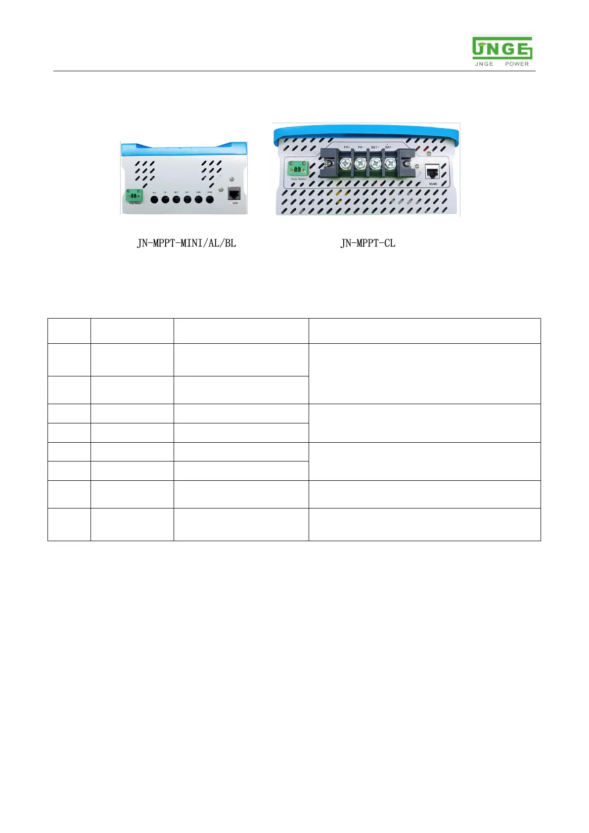
3.2.Interface definition
pic2-2 Product interface definition
Table 2-2 Product interface definition
Photovoltaic array
positive electrode
Photovoltaic array
negative
DC load output (JN-MPPT-CL does not
have this output)
External temperature
test terminal
Measuring battery temperature
Realize the monitoring of host computer,
WIFI and GPRS communication
III. Installation Instruction
1. installation precautions
(1) You must read the entire installation chapter and familiarize yourself with the installation
steps before installation.
(2) Be very careful when installing the battery. For the installation of the open lead-acid
battery, wear a protective mirror. When it comes into contact with the battery acid,
please rinse it with clean water.
(3) Avoid placing metal objects near the battery to prevent the battery from short-circuiting.
 Loading...