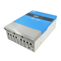
JN-MPPT Buck series solar charge controller
address:no.99 yonghe road.Hefei.Anhui.China Tel:0551-65372576 http://www.hfjnge.com
3. Wire
Note: For installation safety, we recommend a wiring sequence
Note: The MPPT series controller is a common negative design.
Caution: Do not connect the electrical equipment that exceeds the surge power of
the controller to the load terminal to prevent damage to the controller!
Warning: When you need to use the mobile, make sure that all the wirings are fixed.
Because the virtual connection points may cause heat to accumulate, it may cause
fire in severe cases;
Step 1: Connect the battery, PV module, load, temperature sensor, monitoring
background.
Connect the battery, load, PV module, temperature sensor, monitoring background
(host computer / WIFI module / GPRS module) in turn, disconnect all switches during the
wiring process, pay attention to distinguish between positive andnegativeBefore connecting
the battery, make sure the battery is in a normal state to ensure normal operation of the
system.egative cable access.
Warning: Do not connect the PV panel to the battery terminal of the controller, as it
will burn out the controller.It is strictly forbidden to make the battery positive or
negative, extremely short circuit, otherwise it will cause fire or explosion hazard,
Step 2:Wiring diagram
Lock the cable to the binding post through the mounting hole on the lower side of the
cabinet.
pic2-2 Wiring diagram
 Loading...