4610, 4615, 4620P, 5610, 5610D, 5610L, 5610P, 5610Q, 5610VL,
5610VQ, 5611, 5611L, 5611Q, 5615, 5615L, 5615Q, 5620, 5620D, 5620P,
5620VP, 5620V, 5625, 5625P, EZ-1, FFET, SB1, SB1A, SB2, SB2A, SBW
STANDARD CARTRIDGE SEALS
Installation, Operation & Maintenance Instructions
5
TYPE
Before installing the mechanical seal read the instructions carefully. Keep
for future use. Seal installation must only be carried out by a suitably
qualified person.
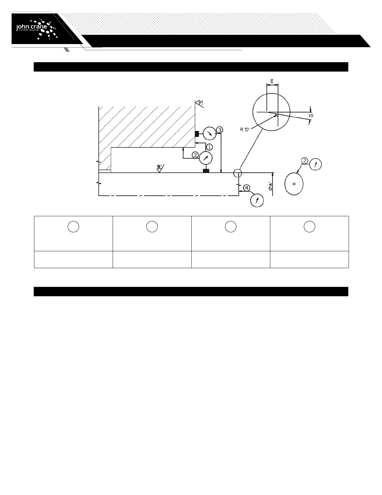
1. Check that the machine is clean and meets the fitting tolerances shown
in the figure above. (Misalignment can lead to excessive friction on the
PTFE centering device on 4610, 4620, EZ-1 and 4615 range).
2. Unpack cartridge, inspect for damage, wipe clean.
3. Lubricate the machine shaft or sleeve with a recommended lubricant.
See Recommended Properties of Barrier Liquids for Dual Seals, page 9.
4. Slide the cartridge on to the machine shaft or sleeve and rotate until the
barrier inlet port ports are in a suitable position for flush piping.
5. Ensure that gland plate sealing ring is in position then slide the cartridge
against the seal chamber.
6. Fit the gland plate fasteners and evenly tighten to the torque
recommended by the machine manufacturer.
7. Ensure the machine shaft is locked axially in its final correct position and
evenly tighten the cartridge drive collar socket set screws. See Table 1 or
Table 2 depending on cartridge type for torque values.
8. Remove any setting clips or spacers and store for future use in cartridge
removal. For EZ-1, 4610, 4615 and most 4620P seals there are no setting
clips to remove.
9. Turn the machine shaft by hand if possible to ensure free rotation with no
shaft binding.
10. Complete the required piping to the seal. See pages 6 and 7. Take care
not to use excessive thread sealant when making circulation pipe work
connections. Unused tapped connections must be safely plugged before
seal operation.
11. Ensure machine seal chamber and seal are safely vented before starting
the machine. This should be achieved through self-venting pipework.
When manual vents are necessary they must be installed and used
safely.
12. For liquid lubricated dual seals ensure that the seal lubrication system
is correctly filled with suitable liquid. See Recommended Properties of
Barrier Liquids for Dual Seals on page 9 for guidance on liquid selection.
13. For a dual pressurized arrangement ensure that the seal is pressurized to
a minimum of 1bar above the maximum machine seal chamber pressure
before the machine is pressurized. The seal pressure must be within the
seal and seal lubrication system operating pressure.
Once fitted, no adjustment is possible during the life of the mechanical
seal. When the mechanical seal requires replacement, John Crane can
supply a new or reconditioned seal to the original specification.
A – Seal size
B – 0.2-0.5 μm Ra
8-20 μinch Ra
C – 1.6-3.2 μm Ra
63-125 μinch Ra
D – 1.0 mm/0.040 inch
E – 1.5 mm/0.060 inch
1
Squareness of shaft
to seal chamber face
2
Concentricity seal
chamber bore to shaft
3
Shaft runout
4
Shaft end play
0.001 mm/mm diameter
0.001 inch/inch diameter
<0.13 mm FIM
<0.005 inch/FIM
<0.05 mm FM
<0.002 inch/FIM
<0.13 mm FIM
<0.005 inch/FIM
Installation Instructions
Checking the Machine
 Loading...