4610, 4615, 4620P, 5610, 5610D, 5610L, 5610P, 5610Q, 5610VL,
5610VQ, 5611, 5611L, 5611Q, 5615, 5615L, 5615Q, 5620, 5620D, 5620P,
5620VP, 5620V, 5625, 5625P, EZ-1, FFET, SB1, SB1A, SB2, SB2A, SBW
STANDARD CARTRIDGE SEALS
Installation, Operation & Maintenance Instructions
9
TYPE
•
For dual seals on a vertical shaft the barrier outlet should be above the
upper seal faces to ensure self-venting. The flush connection should be
above the level of the lower faces.
•
For a thermosiphon system, follow the piping layout on page 8. A
pumping ring is always recommended for use with a thermosiphon
system.
Notes
•
In a dual unpressurized arrangement the inboard seal is cooled and
lubricated by the pumped liquid at seal chamber pressure. The outboard
seal is lubricated by the barrier liquid typically at atmospheric or flare
pressure.
•
In a dual pressurized arrangement both seals are cooled and lubricated
by the barrier liquid maintained at a pressure higher than the seal
chamber pressure. This arrangement isolates the pumped liquid from
the atmosphere.
Alternative Terms for Gland Plate Ports
I, BI, LBI – Buffer/barrier inlet Q – Quench
O, BO, LBO – Buffer/barrier outlet F – Flush
D – Drain H – Heating (applies to jacket when fitted)
V – Vent C – Cooling (applies to jacket when fitted)
Recommended Properties of Barrier Liquids for Dual Seals
•
A good lubricant with good heat transfer properties
•
Clean
•
Compatible with the process fluid and seal materials of construction
•
Stable over the seal’s operating range
•
Non-hazardous
•
A viscosity < 15 cSt/80 SSU @ 40°C/104°F and ideally between
1 and 10 cSt/31 to 60 SSU @ 65°C/150°F
•
A maximum viscosity of 680 SSU/150 cSt at the minimum ambient
temperature
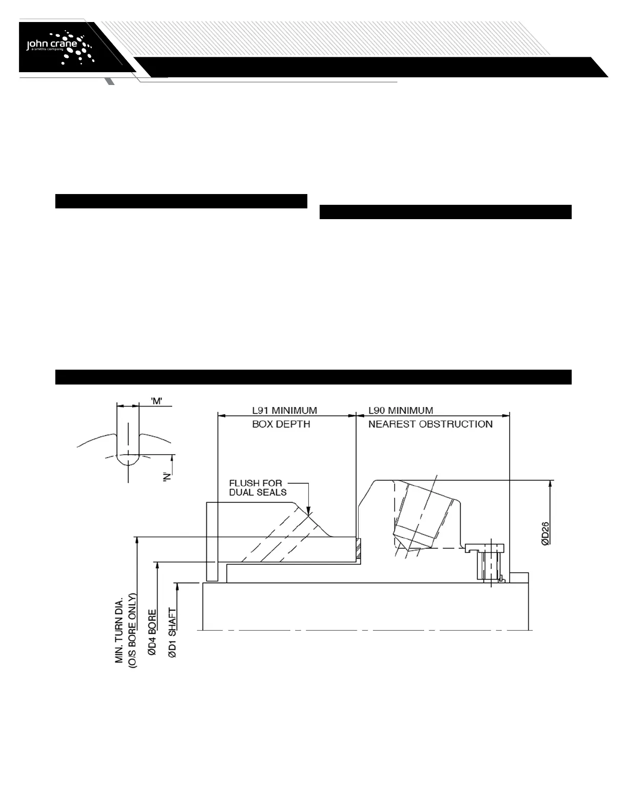
Seal Dimensions