IMPORTANT: If MENU is not pressed after
changing the setpoint value, the control reverts to
the previously programmed setpoint value.
MENU
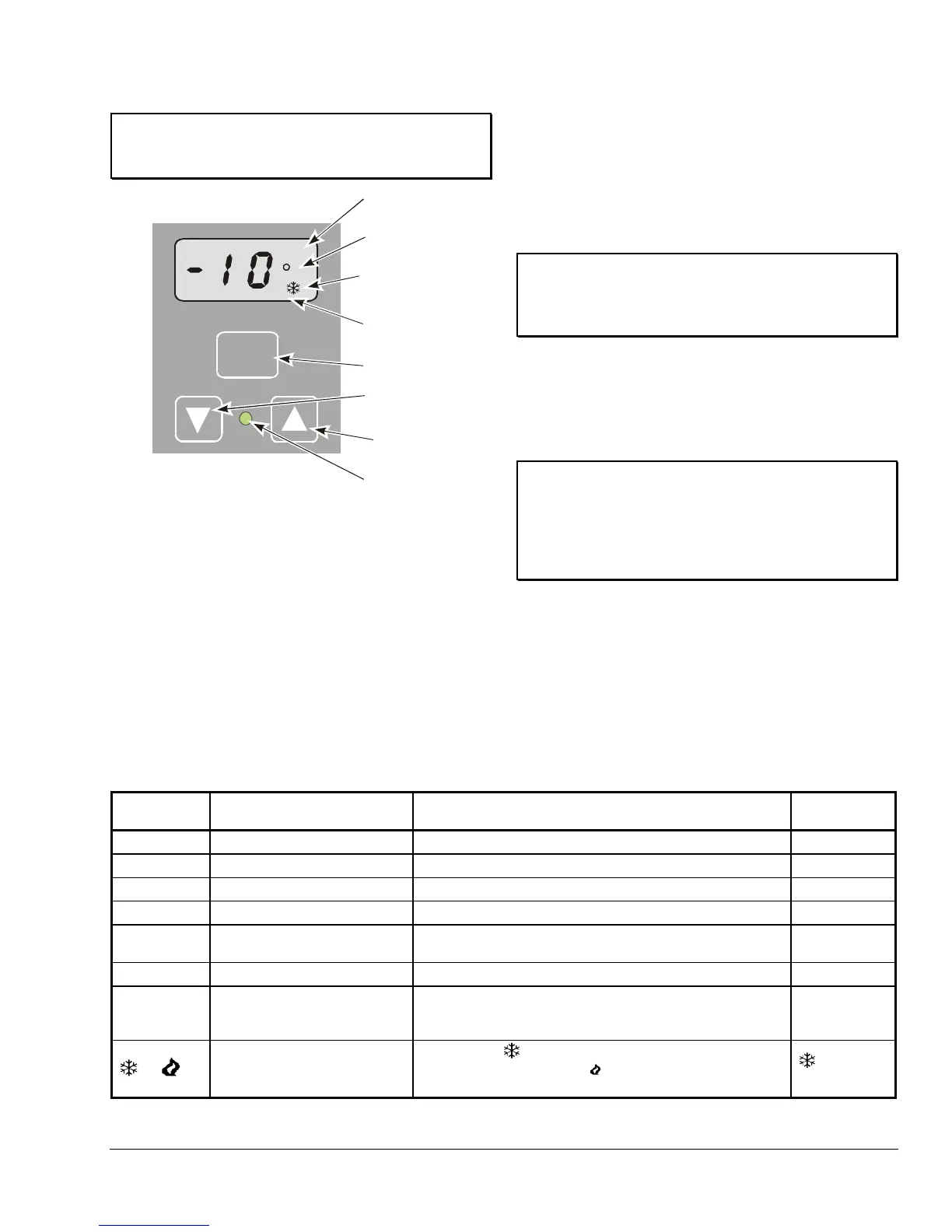
F
BIN
MENU
Button
DOWN
Arrow
Button
UP
Arrow
Button
Output Relay
Status Indicator
LED
Operating Mode
Indicator
Temperature
Units Indicator
Temperature
Offset Indicator
Liquid Crystal
Display
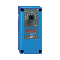
Figure 6: Liquid Crystal Display, Touchpad, and
LED Indicator
Setting the Other A419 Control Functions
To set the Differential, Anti-short Cycle Delay,
Temperature Offset, or Sensor Failure operation, use
the following method.
1. Press and hold MENU until the display changes to
flashing SP. (This takes about 2 seconds.)
2. Press Up or Down (arrows) repeatedly until the
desired function is displayed. (See
Table 3.)
3. Press MENU to display the function’s current
value.
4. Press Up or Down (arrows) until the desired value
is displayed.
5. Press MENU to save the new value. The display
returns to the sensor temperature.
IMPORTANT: If MENU is not pressed after
changing the settings, the new settings are not
saved and the control reverts to the previously
programmed setting values.
Note:
Note:
If no setup entry is made for 30 seconds, the
control reverts to the (normal) temperature display.
Any saved A419 control settings are
non-volatile and remain in the control’s memory
during power interruptions.
IMPORTANT: Do not set Setpoint and
Differential values which (when totaled) fall out of
A419 control’s Setpoint range (-30 to 212°F
[-34 to 100°C]). The control will not function properly
if Cut-in or Cutout values are outside of the control’s
Setpoint range.
Checkout
Before applying power, make sure installation and wire
connections are correct for your application. Then
power, operate and observe the system and A419
control for at least three complete operating cycles
before leaving the installation.
Table 3: Display Symbols, Control Function, Ranges, Units, Values, and Factory Settings
Display
Symbol
Control Function Range – Units/Value
Factory Set
Value
SP
Setpoint* -30 to 212 – °F (-34 to 100 – °C) 30
dIF
Differential* 1 to 30 – (F° or C° in 1-degree increments) 5
ASd
Anti-short Cycle Delay 0 to 12 – (in 1-minute increments) 1
OFS
Temperature Offset 0 to 50 (F° or C° in 1-degree increments) 0
SF
Sensor Failure Operation
(No range)— 0 = output relay de-energized
1 = output relay energized
1
F or C
Temperature Units (No range) – F° or C° F°
BIN
Temperature Offset Indicator
(No range) – BIN is displayed and the A419 control
operates on the secondary setpoints when the circuit
between the BIN and COM terminals is closed.
N/A
or
Cooling or Heating Mode of
Operation
(No range) –
(Cooling Mode) is displayed when the
Jump1 jumper is removed.
(Heating Mode) is displayed
when the Jump1 jumper is installed.
Cooling Mode
* The sum of the Setpoint and Differential values must be within the Setpoint range, or the control may not function
properly.
A419 Electronic Temperature Control with NEMA 1 and NEMA 4X Watertight Enclosures Installation Instructions 5

 Loading...