A419GBF-1
24 VAC
Class 2
Transformer
A419GEF-1
240
AC COM
120
NC
C
NO
A419ABC-1
120 VAC
Neutral
A419AEC-1
TB2
TB1
240
AC COM
120
NC
C
NO
A419ABC-1
240
VAC
A419AEC-1
TB2
TB1
T1
T2
NC
C
NO
TB2
TB1
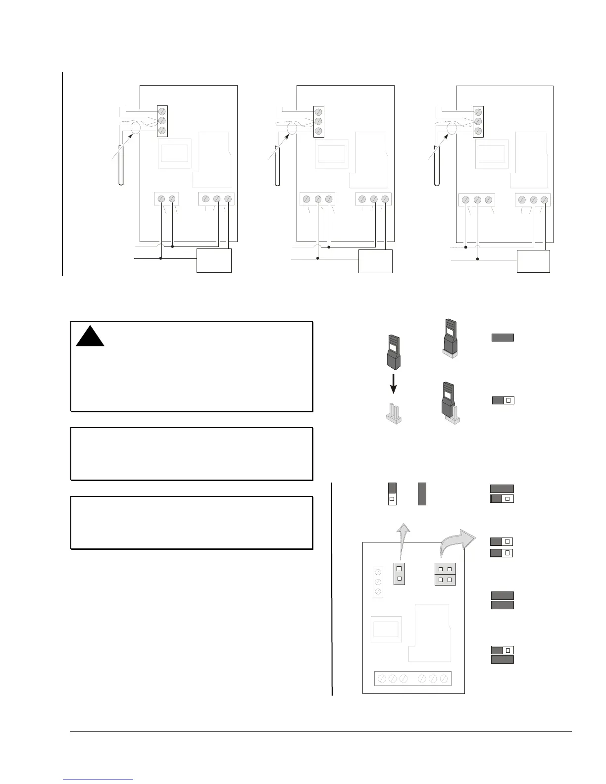
24 VAC Application
120 VAC Application 240 VAC Application
Cable
Shield
(if used)
TB3
(+)
(+)
(–)
(Optional)
Binary
Input
Switch
BIN
SEN
COM
A99
Sensor
Cable
Shield
(if used)
TB3
(+)
(+)
(–)
(Optional)
Binary
Input
Switch
BIN
SEN
COM
A99
Sensor
Cable
Shield
(if used)
TB3
(+)
(+)
(–)
(Optional)
Binary
Input
Switch
BIN
SEN
COM
A99
Sensor
L1
L2
24 VAC
Load
120 VAC
Load
240 VAC
Load
Figure 3: Typical Wiring for the A419 Series Temperature Controls: 24, 120, and 240 VAC Applications
Setup and Adjustments
!
WARNING: Risk of Electrical Shock.
To avoid the risk of electrical shock disconnect all
power sources to the control before opening control
cover and repositioning jumpers. More than one
disconnect may be required to completely
de-energized the control and equipment.
IMPORTANT: To ensure that the output relay
operates as intended, verify that all three of the
jumpers are positioned properly for the application
before powering the A419 control.
IMPORTANT: The touchpad cannot be
unlocked without a jumper installed across the P5
jumper pins. Do not discard jumpers in case they are
required in the future. See Figure 4 and Figure 5.
Positioning the Jumpers
The P5 jumper position determines if the touchpad is
locked or unlocked.
The P4 jumper pin block has two pairs of jumper pins.
The top pair of pins (JUMP1), determines if the control
is set for Heating or Cooling mode. The bottom pair of
pins, (JUMP2) establishes whether Setpoint is at cut-in
or at cutout. See
Figure 4 and Figure 5.
To position a jumper in the Installed position, place
the jumper on both pins, which closes the circuit
between the pins. To position a jumper in the
Removed position, place the jumper on one pin only.
See
Figure 4.
Jumper
Pins
Removed
(Jumper Positioned on One Pin)
Installed
(Jumper Positioned on Both Pins)
=
=
Figure 4: Positioning the Jumpers
P5
P4
Touchpad
Locked
Touchpad
Unlocked
Heating Mode
Cut-in at Setpoint
Heating Mode
(Standard)
Cut-out at Setpoint
Cooling Mode
(Standard)
Cut-out at Setpoint
Cooling Mode
Cut-in at Setpoint
JUMP1
JUMP2
Figure 5: Jumper Positions and Control Settings
A419 Electronic Temperature Control with NEMA 1 and NEMA 4X Watertight Enclosures Installation Instructions 3

 Loading...