Do you have a question about the Johnson Controls A419 Series and is the answer not in the manual?
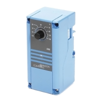
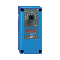
Single-stage electronic temperature controls with SPDT output relay, LCD display, and NEMA 1 or NEMA 4X enclosures.
Displays sensed temp, status, and custom icons for control and system status.
Allows precise temp diff setting (1-30F°/C°) for tighter control than electromechanical units.
Prevents rapid cycling by maintaining relay off-time, protecting equipment.
Shifts cut-in/cutout setpoints based on an external switch, like a time clock.
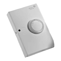
Offers NEMA 1 for surface/DIN rail and NEMA 4X for watertight, corrosion-resistant applications.
Enables easy setup/adjustment, with a jumper to lock touchpad and deter unauthorized changes.
Provides options for most refrigeration and HVAC control-voltage applications.
Controls are for normal operation; safety devices must be integrated to protect against failure or malfunction.
Used for refrigeration, HVAC equipment like freezers, coolers, boilers, and fans.
Details compliance with FCC Part 15 rules and Canadian Radio Interference Regulations.
Explains the front panel components (LCD, LED) and how control functions are described.
Details the Liquid Crystal Display (LCD), Output Relay Status Indicator LED, and touchpad buttons for operation.
Defines Cut-in (relay closes) and Cutout (relay opens) temperatures relative to the SPDT output relay.
Covers Setpoint (SP), Differential (dIF), and Anti-Short Cycle Delay (ASd) adjustment via the front panel.
Defines operation during sensor or sensor-wiring failures (continuous run or shutdown).
Covers changing display units (F°/C°) and applying temperature offset via binary input.
Explains how jumpers set Touchpad Lock, Heating/Cooling mode, and Setpoint mode (cut-in vs. cutout).
Details the four operating modes: Cooling/Cut-in, Cooling/Cutout, Heating/Cut-in, and Heating/Cutout.
Describes NEMA 1 and NEMA 4X enclosures and provides guidance on mounting.
Emphasizes electrical safety, wire types, and provides typical wiring diagrams for different voltage models.
Guidelines for sensor lead length, resistance, interference, and wiring for the Temperature Offset function.
Details jumper placement on P4 and P5 to configure mode, setpoint type, and touchpad lock.
Procedure to convert temperature display between Fahrenheit and Celsius units.
Step-by-step guide for adjusting the temperature setpoint using the control's buttons.
Instructions for adjusting Differential (dIF), Anti-short Cycle Delay (ASd), Temperature Offset (OFS), and Sensor Failure (SF).
Steps to verify installation, wiring, and control operation for three complete cycles before finalizing.
Covers checking voltage, sensor operation (resistance vs. temp), and output relay function based on settings.
Lists fault codes (SF, EE) displayed on the LCD and provides corresponding system status and solutions.
Advises against self-repair; provides guidance on contacting distributors and ordering information.
Details specifications including range, voltage, power, electrical ratings, and environmental conditions.
| Brand | Johnson Controls |
|---|---|
| Model | A419 Series |
| Category | Temperature Controller |
| Language | English |