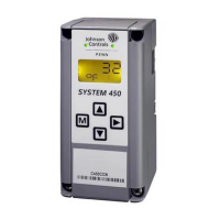
Table 2: C450CCU menu blocks
Screens Description
30-39 Mode configuration screens:
• 30: The MOdE configuration menu. Use the screens in this menu to configure the control function options and assign relay outputs
that the refrigeration system uses.
• 31: Use this screen to allocate a relay output as the refrigeration output relay. In a pump down application, the refrigeration output
is normally a liquid line solenoid valve. In a non-pump down application, the refrigeration output is normally a compressor. You
can choose from the following refrigeration outputs: r1, r2, r3, r4, r4, r5, or r6. The default refrigeration output is r1 on the first
initialization.
• 31a: Use this screen to configure the behavior of the refrigeration output relay or REFR that relates to the status of the output. You
can choose to energize the relay coil, when the status of the output is set to ON or OFF. This parameter depends on the wiring of
the controlled equipment through the associated relay contacts, N.O. or N.C, to provide a fail-safe state in the event of controller
failure or loss of power. The default value is OFF.
• 32: Use this screen to configure the type of evaporator fan. You can choose from the following options: EF-1 for a single-speed fan
or EF-2 for a two-speed fan. The default setting is single-speed fan.
• 33: Use this screen to allocate one of the relay outputs as the single-speed or high-speed evaporator fan output relay. You can
choose from the following relay outputs: r1, r2, r3, r4, r5, or r6. The default relay output for the first initialization is r2.
• 33a: Use this screen to configure the behavior of the Evaporator Fan 1 or high-speed fan output relay. You can choose to energize
the relay coil, when the status of the output is set to ON or OFF. This parameter depends on the wiring of the controlled equipment
through the associated relay contacts, N.O. or N.C., to provide a known fail safe state in the event of controller failure or loss of
power. The default value is OFF.
• 34: Use this screen to allocate one of the relay outputs as a low-speed evaporator fan output relay. This screen is visible if the ETYP
parameter in screen 32 is EF-2. You can choose from the following relay outputs: --, r1, r2, r3, r4, r5, or r6. The default relay output is
None or --.
• 34a: Use this screen to configure the behavior of the Evaporator Fan 2 or Low-speed fan output relay. You can choose to energize
the relay coil, when the status of the output is ON or OFF. This parameter depends on the wiring of the controlled equipment
through the associated relay contacts, N.O. or N.C., to provide a known fail safe state in the event of controller failure or loss of
power. The default value is ON.
• 35: Use this screen to set the type of defrost that the system uses. You can choose either passive or active defrost: PASS or ACt. The
default defrost type is PASS.
• 36: Use this screen to allocate one of the relay outputs as the defrost heater output relay. This screen is visible if the defrost
parameter in screen 35 is set to ACt. You can choose from the following relay outputs: --, r1, r2, r3, r4, r4, r5, or r6. The default relay
output is None or --.
• 36a: Use this screen to configure the behavior of the defrost output relay. You can choose to energize the relay coil, when the status
of the output is set to ON or OFF. This parameter depends on the wiring of the controlled equipment through the associated relay
contacts, N.O. or N.C., to provide a known fail-safe state in the event of controller failure or loss of power. The default value is ON.
• 37: Use this screen to enable or disable the pump down feature. You can choose from dIS or EnA. The default setting is dIS.
• 38: Use this screen to allocate one of the relay outputs as the pump down output relay. This screen is visible only if the pump down
in screen 37 is EnA. You can choose from the following relay outputs: --, r1, r2, r3, r4, r5, or r6. The default relay output is None or --.
• 38a: Use this screen to configure the behavior of the pump down or compressor output relay. You can choose to energize the relay
coil, when the status of the output is ON or OFF. This parameter depends on the wiring of the controlled equipment through the
associated relay contacts, N.O. or N.C., to provide a fail-safe state in the event of controller failure or loss of power. The default
value is OFF.
• 39: Use this screen to allocate one of the relay outputs as an alarm output relay. By default, the alarm output energizes when
you connect power and remains on while there are no alarms active. During any active alarm condition, the alarm output relay
deenergizes. You can choose from the following alarm relay outouts: --, r1, r2, r3, r4, r5, or r6. The default relay output is None or --.
• 39a: Use this screen to configure the behavior of the alarm output relay. You can choose to energize the relay coil, when alarms are
active or deactive. This parameter depends on the wiring of the controlled equipment through the associated relay contacts, N.O.
or N.C., to provide a fail-safe state in the event of controller failure or loss of power. The default value is OFF. Alarms remain active
within the controller even if an alarm relay is not defined.
40-44 Refrigeration configuration screens:
• 40: This is the REFR configuration menu. Use the screens in this menu to configure the parameters the refrigeration output uses.
• 41: The target temperature for the refrigerated space displays on this screen and acts as the cut-out setpoint. When the measured
space temperature is less than or equal to the setpoint, the refrigeration output turns off. Limits: -40°F to 122°F or -40°C to 50°C.
The default value is 35°F or 1.7°C.
• 42: On this screen, you can view the temperature differential that is added to the setpoint for the refrigerated space to provide a
cut-in setpoint. Limits: 1°F to 15°F or 1°C to 8°C. The default value is 3°F or 1.5°C.
• 43: Use this screen to configure the action to take in the event of a space temperature sensor failure on input Sn-1. You can choose
from the following options: ON, OFF or CYC. The default state is ON.
Note: CYC: Cycling at a rate equal to the average rate of the last 4 ON or OFF cycles prior to the failure of the Sn-1 sensor.
• 44: Use this screen to display the minimum time a refrigeration output can remain off. When the refrigeration output is off, it
remains off for a period of time no less than the ASd. This feature prevents the rapid On/Off transitions of the compressor or short-
cycling. Limits: 0-12min. The default time is 1min.
50-53 Pump down configuration screens
• 50: This is the PdWn configuration menu. Use this screen to configure the parameters that are used in the control of the pump-
down output. This menu is only visible if the PdWn screen is set to EnA.
• 51: Use this screen to set the ON setpoint for pump down. The ON setpoint is the pressure at which the compressor is cut on to
start the pump down of the system. Limits: P110 Sensor = 0.0 to 100.0 psi, P110 Sensor = -10.0 to 100.0 psi, P200 Sensor = 0 to 200
psi, P8 Sensor = -1.0 to 8.0 bar and P15 Sensor = -1.0 to 15.0 bar. Default values: 25 psi and 1.7 bar.
• 52: Use this screen to configure the OFF setpoint. The OFF setpoint is the pressure at which the compressor is cut off to stop the
pump down of the system. Limits: P110 Sensor = 0.0 to 100.0 psi, P110 Sensor = -10.0 to 100.0 psi, P200 Sensor = 0 to 200 psi, P8
Sensor = -1.0 to 8.0 bar and P15 Sensor = -1.0 to 15.0 bar. Default values: 15 psi and 1.0 bar.
• 53: Use this screen to configure the action to take in the event of a suction pressure sensor failure on the input Sn-3. You can
choose one of the following options: ON or OFF. The default setting for the compressor is ON.
11System 450 Series C450CCU Condensing Unit Control System Technical Bulletin

 Loading...


