System 450™ Series Control Modules with Relay Outputs Installation Instructions 17
Table 10: System 450 Setup Screen Information and Procedures for Relay Outputs with Differential Control
(Part 1 of 2)
LCD Screen Name, Description/Function, Procedures, and Example
Relay Output Setup Start Screen: The output numbers and the output type (relay or analog) are
determined by the module types and configuration of your control system’s module assembly and are
automatically assigned when you connect power to the module assembly. (See Setting Up a Control
System in the User Interface on page 5.)
Note: You must set up the system’s sensors before you can set up the system outputs, and you must set
up the Differential Control sensor (Sn-d) before you can set up an output with Differential Control. (See
Setting Up System 450 Sensors
for information on setting up the Differential Control sensor.)
1. Press to go to this output’s Sensor Selection screen.
The screen example shows the Relay Output Setup Start screen for Output 1.
Sensor Selection Screen: Selecting the Differential Control sensor (Sn-d) here establishes this output
as a Differential Control output. Differential Control outputs have several different setup parameters and
value ranges from standard and High Input-Signal Selection outputs.
Note: To set up an output for Differential Control, the Differential Control sensor (Sn-d) must be already
set up in the System 450 UI (See Setting Up System 450 Sensors
for more information.), and you must
select Sn-d in the Sensor Selection screen. If Sn-d is not selected here, the Differential Control setup
screens do not appear. If a sensor is already selected for this output, the Sensor Selection screen does
not appear here, instead the Relay ON Selection screen (ON or dON) appears.
2. Press or to select the Differential Control sensor (Sn-d) as the sensor this output
references. Press to save your sensor selection and go to the Relay dON Selection Screen.
The screen example shows Sn-d is the selected Sensor for Output 1.
Relay dON Selection Screen: Select the dON value at which the relay turns on. The dON value is a
differential value that represents the intended difference in the condition (temperature, pressure, or
humidity) between Sn-1 and Sn-2 (Sn-1 minus Sn-2) at which the relay is turned on. Depending on the
intended control action and the physical location of Sn-1 and Sn-2 sensors in the condition process, dON
may be a positive or negative value. Relay dON is defined as relay LED On/Lit, relay contacts N.O. to C
are closed, and N.C. to C contacts are open.
Note: The unit of measurement, resolution increment, minimum control band, and range of usable
values for dON and dOFF are determined by the Sensor Type selected for Sn-1 and Sn-2. (See Table 3
and Table 9 for more information.)
3. Press or to select the differential value at which the output relay turns On. Press to
save your selection and go to Relay dOFF Selection Screen.
The screen example shows a dON value of 28 (psi) selected for Relay Output 1.
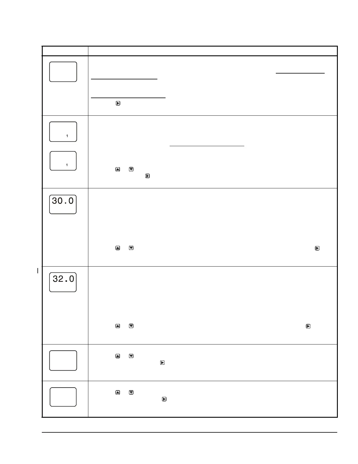
Relay dOFF Selection Screen: Select the dOFF value at which the relay turns off. The dOFF value is a
differential value that represents the intended difference in the condition (temperature, pressure, or
humidity) between Sn-1 and Sn-2 (Sn-1 minus Sn-2) at which the relay is turned off. Depending on the
intended control action and the physical location of Sn-1 and Sn-2 sensors in the condition process,
dOFF may be a positive or negative value. dOFF is defined as relay LED Off, relay contacts N.C. to C are
closed, and N.O. to C contacts are open.
Note: The unit of measurement, resolution increment, minimum control band, and range of usable
values for dON and dOFF are determined by the Sensor Type selected for Sn-1 and Sn-2. (See Table 3
and Table 9 for more information.)
4. Press or to select the differential value at which output relay turns Off. Press to save
your selection and go to Minimum Relay ON TIme Selection Screen.
The screen example shows a dOFF value of 30 (psi) selected for Relay Output 1.
Minimum Relay ON Time Selection Screen: Minimum ON Time range is 0 to 300 seconds.
5. Press or to select the minimum time that the output relay remains On after reaching the
Relay dON value. Press to save your selection and go to the Minimum Relay OFF Time
Selection Screen.
The screen example shows an ONT value of 0 (seconds) selected for Output 1.
Minimum Relay OFF Time Selection Screen: Minimum OFF Time range is 0 to 300 seconds.
6. Press or to select the minimum time that this output relay remains Off after reaching the
Relay dOFF value. Press to save your selection and go to the Sensor Failure Mode Selection
screen.
The screen example shows an OFFT value of 30 (seconds) selected for Output 1.
--
Sn-d
dON
dOFF
 Loading...