System 450™ Series Control Modules with Relay Outputs Installation Instructions 21
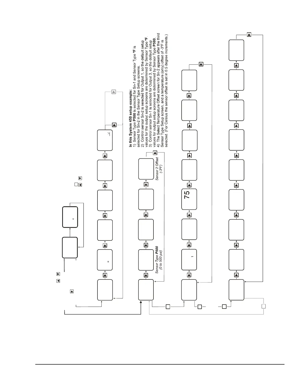
Figure 7: System 450 Status Screens, Setup Screens, and Menu Flow Example
Relay Output
Setup Start
OUTR
1
-- -
Sensor 2 Selected.
(Displayed only when a
Sensor is selected.)
not
Up to
ten
Outputs
can be
connected
and
set up.
M
Relay
Output
1
OUTA
3
OutputAnalog
Setup Start
Analog
Output
3
Select Relay ON
Value
ON
1
78
Relay
at ºF
1ON
78
OFF
1
Select Relay OFF
Value
Relay
at ºF
1OFF
75
Select Min
imum
Time
ONT
1
0
Relay
Seconds
(Minimum)
1ON
0
Select Sensor
Failure Mode
SNF
1
OFF
Relay
if Sensor 2 Fails
1OFF
Select Minimum
Relay OFF Time
OFFT
1
120
Relay
Seconds
(Minimum)
1OFF
120
Select
Setpoint Value
Prop. Band
SP
3
200
Analog Output
Prop. Band
Setpoint psi
3
200
Sele
ct Prop. Band
Point Value
EP
3
250
log Output
rop. Band
Point psi
3
250
Select Integration
Constant Value
I-C
3
0
Analog Output
Integration
Constant
3
No
Select % Output
Signal Value
at Setpoint
OSP
3
10
Output Signal %
of Range at
Value
10
Setpoint
Select % Output
Signal Value
at End Point
OEP
3
90
Output Signal %
of Range at
Value
90
End Point
Select Sensor
Failure Mode
SNF
3
OFF
Analog Output
if
Sensor 1 Fails
3
OFF
FIG:menu_flw_chrt
M
232
PSI
1
Main Screen
Sensor 2 Status
74
2
F
Main Screen
Sensor 1 Status
Up to ten Outp
uts
and
displayed.
Relay Output 2
Status
OFF
OUT
2
Output 2 Relay
OFF
Relay Output 1
Status
OUT
1
Output 1 Relay
On
Analog Output 3
Status
61
OUT
3
Output 3 Signal
at % of Range
61
Control Sensor 3
Status
----
3
Control Sensor 3
Not Set Up
Control Sensor 2
Status
74ºF
74
2
F
232
PSI
1
Control Sensor 1
Status
232 psi
Sensor Setup
Screens
System Status
Screens
Main Screens
(Sensor Status)
Relay Output
Setup Screens
Analog Output
Setup Screens
M
Press and hold +
for 5 seconds to go to
the Setup Start screens.
Press to scroll through
Sensor Status screens and
Output Status screens.
Select
Control Sensor
Sn-2
SENS
SENS
Sensor Type
Setup Start
-- -
Select Sensor 2
Type
°F
Sensor Type
(-40 to 250ºF)
ºF
Select Sensor 3
Type
--
No
Sensor Type
Selected
Select Sensor 1
Type
P500
Sn-1
Sn-2 Sn-3
SENS
3
Edit
Control Sensor
Sensor (Sn-1)
Controls
Analog Output
1
3
Sn-1
Select
Control Sensor
SENS
3
Sensor 1 Selected
(Displayed only
when a Sensor
is selected.)
not
Sn-1
Edit
Control Sensor
Sensor (Sn-2)
Controls Relay
2
1
SENS
1
Sn-2
ly)
s
-3
OFFS
During normal operation, the display automatic
ally scrolls through the Sensor Status screens
for all sensors set up in the UI.
After a 2 minute pause in any setup or status s
creen (below), the display returns to the
Main (Sensor Status) screens.
Press in any Setup screen to go to the asso
ciated Setup Start screen.
Press + simultaneously in any Setup Star
t screen to return to the Main screen.
M
On
2
M
-- -
Output 2
Setup Start
Screen