DIS1710 Local Controller Display Installation
Instructions
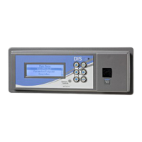
Applications
The DIS1710 Local Controller Display is a stand-
alone display module designed for installation on
the front panel of an enclosure. The DIS1710 display
can connect to the Network Control Engine (NCE),
Field Equipment Controller (FEC), or Advanced
Application Field Equipment (FAC) models that do
not have integral displays. The display provides a
local user interface for the application running in
the controller. Use the Controller Configuration Tool
(CCT) tool to configure the display.
North American emissions
compliance
United States
This equipment has been tested and found to
comply with the limits for a Class A digital device
pursuant to Part 15 of the FCC Rules. These limits
are designed to provide reasonable protection
against harmful interference when this equipment
is operated in a commercial environment. This
equipment generates, uses, and can radiate radio
frequency energy and, if not installed and used in
accordance with the instruction manual, may cause
harmful interference to radio communications.
Operation of this equipment in a residential area
may cause harmful interference, in which case the
users will be required to correct the interference at
their own expense.
Canada
This Class (A) digital apparatus meets all the
requirements of the Canadian Interference-Causing
Equipment Regulations.
Cet appareil numérique de la Classe (A) respecte
toutes les exigences du Règlement sur le matériel
brouilleur du Canada.
Installation
Observe these guidelines when installing the
DIS1710 display:
• Transport the display in the original container to
minimize vibration and shock damage to the unit.
• Verify that all parts were shipped with the display.
• Do not drop the display or subject it to physical
shock.
Parts included
• One DIS1710 Local Controller Display
• One communication cable
• One O-ring
• One installation instructions sheet
Materials and special tools needed
• Power saw for cutting a hole into the panel to hold
the display, if no hole is provided
• Small Phillips-head screwdriver
*24102409J*
Part No. 24-10240-9 Rev. J
2019-10-18
(barcode for factory use only)
MS-DIS1710-0