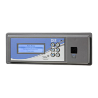
Figure 3: DIS1710 Panel Cutout Dimensions, mm/
in.
Mounting display to enclosure door
Follow these steps to mount the display onto the
front of the enclosure door (Figure 5):
1. Loosen the two thumbscrews on the back plate,
but do not remove them.
2. Detach the back plate from the display by using
a small Phillips-head screwdriver to remove
the two back plate screws. Tilt the back plate
forward to remove it from the retaining tabs.
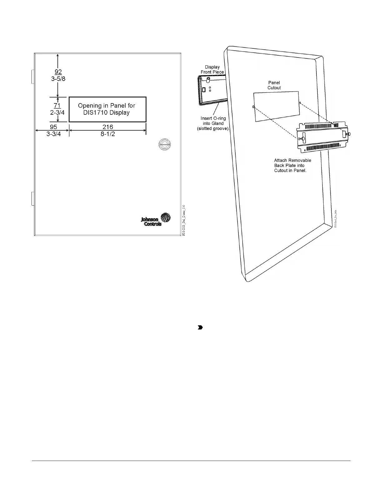
3. Insert the O-ring into the gland (slotted groove)
in the back of the display (Figure 4).
4. Insert the display into the front access hole on
the panel door. Hold in place.
5. Carefully insert the back plate to the other side
of the access hole (inside of the panel door) and
secure it to the cutout by hand-tightening the
two thumbscrews. You may need to tilt the back
plate to slide it onto the two bottom retaining
tabs.
Figure 4: Attaching the display into panel cutout
6. Using the screwdriver, tighten the two back
plate screws to secure the back plate in place.
Tighten the thumbscrews against the panel to
provide a snug fit.
Important: Do not overtighten the
thumbscrews. Overtightening the screws may
exert too much pressure on the back plate.
DIS1710 Local Controller Display Installation Instructions 3