Compatibility
Use the Johnson Controls DP150 transducers with air or
nonconducting gases.
Note: Use with liquids or corrosive gases will
damage the unit.
The operating temperature limits of the DP150 are as
follows:
• Operating temperature: 32°F to 122°F (0°C to 50°C)
• Compensated temperature range: 32°F to 122°F (0°C to
50°C)
Mounting
About this task:
Mount and calibrate the DP150 in a vertical position for
quick and easy installation on ducts, walls, or ceilings
and in control rooms. The DP150 comes calibrated as if
mounted to a wall or a perpendicular surface to the floor
or ceiling. If you mount the DP150 in another orientation,
the unit may show a slight zero shift. See Zero adjustment
to correct the zero shift.
Installation
About this task:
The DP150 has a removable terminal block for easy
wiring. For CE compliance, you require a shielded cable
with both ends correctly grounded.
To install the DP150 transducer, complete the following
steps:
1. Wire and turn on the unit. See Figure 2 for 2-wire
configuration and Figure 3 for 3-wire configuration.
2. After you complete wiring requirements, turn on
the DP150.
3. Turn on the LCD unit. Display toggles through all
existing setup parameters.
4. The display indicates the pressure. Units are either
in inches of WC or Pa.
5. Select pressure range. Use the slide switch
multiplier and JMP4 jumper to set the appropriate
full-scale range. See Figure 4.
Note: A to D is WC, E to H is Pa. LCD will
indicate the selected range. To select E-H
position, move JMP to Pa position.
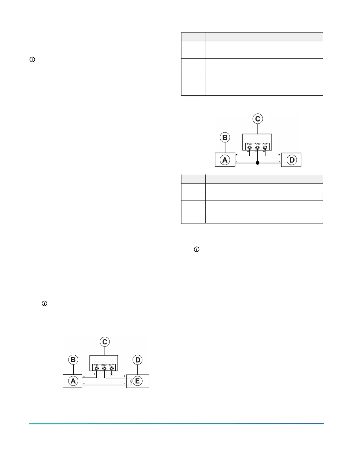
Figure 2: DP150 2-wire configuration
Callout Description
A Power supply, 13 V to 30 V
B 24 VAC, DC only, nominal excitation
C Multi-sense current, 2-wire, 4 mA to 20 mA
configuration
D 250 ohm sense resistor for 1 V to 5 V output
measurement
E Current monitor
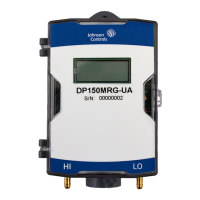
Figure 3: DP150 3-wire configuration
Callout Description
A Power supply, 13 V to 30 V
B 24 VAC or 24 VDC, nominal excitation
C Multi-sense current, 3-wire, 0 VDC to 5 VDC or
0 VDC to 10 VDC configuration
D Voltage monitor
6. Select unidirectional or bi-directional mode.
7. Select current, mA, or voltage: 0 VDC to 5 VDC or 0
VDC to 10 VDC output range. See Figure 4.
Note: If you use 0 VDC to 5 VDC or 5 VDC to
10 VDC outputs, set the mA/volt switch to volt
position.
Figure 4: DP150 range specifications
8. While at zero pressure, press and hold the zero
button until you see 0. Release the zero button to
automatically reset the output to zero.
Optional configuration
About this task:
For optional configuration of the DP150 transducer,
complete the following steps:
1. Press and hold the zero or config button, until you
see 0.
2. Hold down for 7 secs until you see the Conf screen.
3. Release button and screen reads Filt.
4. Hold down button until Filt flashes. Filt is a
sampling filter with 4 options: Nor (normal), SLo
(slow), FAS (fast), and Off (no filter). See Table 2.
5. Press the zero or config button to cycle through the
options.
Differential Pressure Transducer Multi-Range DP150 Series Installation Guide2
 Loading...