EasyManuals Logo

Johnson Controls E-Link User Manual

Johnson Controls E-Link
26 pages
To Next Page IconTo Next Page
To Previous Page IconTo Previous Page
Page #14 background imageLoading...
Page #14 background image
E-Link Gateway Installation Instructions14
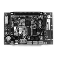
Figure 13: E-Link Gateway Component
Identification
COMMUNICATION CABLE
(OptiView / Latitude)
POWER HARNESS
(OptiView)
4 #8 NYLON WASHERS
(OptiView / Lattitude)
POWER HARNESS
(Latitude)
3/8 in. Screw
8 x 32
(OptiView)
2 Position
Connector
4 Position
Connector
4 Position
Connector
4 Position
Connector
Screw
Tap Thread
M4 x 32 mm
(Latitude)
FIG:OptiVwKt
YMC2
COMMUNICATION CABLE
(OptiView)
YMC2
POWER HARNESS
(OptiView)
4 Position
Connector
4 Position
Connector
YMC2 Communication Cable
Figure 14: E-Link OptiView/Latitude
Installation Kit (YK-ELNKOLK-0)

Questions and Answers:

Question and Answer IconNeed help?

Do you have a question about the Johnson Controls E-Link and is the answer not in the manual?

Johnson Controls E-Link Specifications

General IconGeneral
BrandJohnson Controls
ModelE-Link
CategoryGateway
LanguageEnglish

Related product manuals