EasyManuals Logo

Johnson Controls E-Link User Manual

Johnson Controls E-Link
26 pages
To Next Page IconTo Next Page
To Previous Page IconTo Previous Page
Page #19 background imageLoading...
Page #19 background image
E-Link Gateway Installation Instructions 19
Note: Enabling any of
the Latitude’s PRINT
functions will disrupt
BAS/E-Link
communications.
See YORK Equipment
Form 201.21-NMx in the
Installation, Operation &
Maintenance (IOM)
Air-Cooled Screw Liquid
Chillers manual for more
information.
Note: JP1 on the
031-02478-xxx board
must be set to the
RS485 position when
the E-Link BAS
communication is
required.
Equipment Cable
York Talk 3
Rs232
Optiview Microboard
031-01730-XXX
SHIELD
P
O
R
T
2
B
R
S
232
TX
RX
COM SHLD
(Open)
E-Link
E-Link
+12 VDC
SHIELD
(Open)
Equipment Cable
York Talk 2
RS485
(4800 baud)
SHIELD
+
-
C
O
M
S
H
L
D
P
O
R
T
2
A
R
S
4
8
5
(Open)
E-Link
031-02478-xxx
1
2
3
4
5
Latitude
J16
E-Link
Power
E-Link
+12 VDC
P
O
R
T
2
A
R
S
4
8
5
E-Link
+
_
C
M
S
H
L
D
P
O
R
T
2
B
R
S
232
E-Link
TX
RX
COM
SHLD
Equipment Cable
York Talk 3
Rs232
Optiview Microboard
031-02430-XXX
SHIELD
(Open)
P
O
R
T
2
B
R
S
232
E-Link
E-Link
+12 VDC
SHIELD
(Open)
TX
RX
COM SHLD
FIG:ELnk_OptiLat
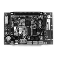
Figure 20: E-Link Gateway to OptiView and Latitude/YCAV/YCIV/YVAA Equipment Connections
(See Table 1 for board cross-reference.)

Questions and Answers:

Question and Answer IconNeed help?

Do you have a question about the Johnson Controls E-Link and is the answer not in the manual?

Johnson Controls E-Link Specifications

General IconGeneral
BrandJohnson Controls
ModelE-Link
CategoryGateway
LanguageEnglish

Related product manuals