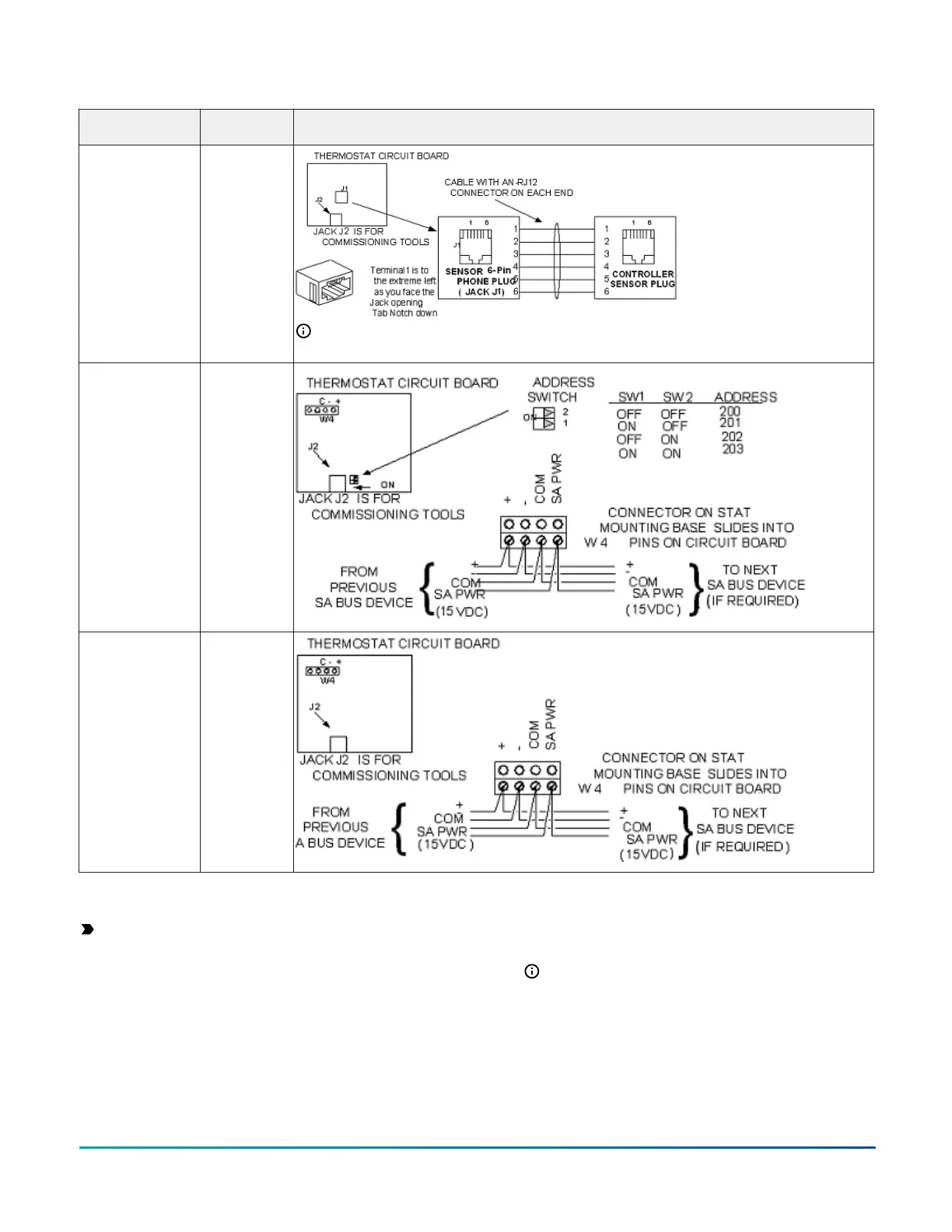
Table 5: Termination details
Type of field
device
Type of Input/
Output
Termination diagrams
Network Stat with
Phone Jack (Fixed
Address = 199)
SA Bus
Note: The bottom jack (J2) on the TE-700 and TE-6x00 Series Sensors is not usable as a zone
bus or an SAB connection.
Network Stat
with Terminals
Addressable
SA Bus
Network Stat with
Terminals (Fixed
Address = 199)
SA Bus
Setup and adjustments
Important: Electrostatic discharge can damage
controller components. Use proper electrostatic
discharge precautions during installation, setup, and
servicing to avoid damaging the controller.
Configuring wireless communications
About this task:
To configure an expansion module for use with the
ZFR183x Pro Series Wireless Field Bus system, complete
the following steps:
1. Disconnect the 24 VAC supply from the expansion
module.
2. Wire the input/output terminals and FC bus.
Note: In wireless network applications, do not
connect any wires to the FC bus terminal block.
3. Important: Before the XPM expansion module
is powered on, connect the ZFR183x Pro Wireless
Field Bus Router to the FC bus port (RJ-12 modular
jack) on the front of the device.
F4-XPM Expansion Modules Installation Guide14
 Loading...


