Hx-68P3 Series Outside Humidity and Temperature Transmitters Installation Instructions 3
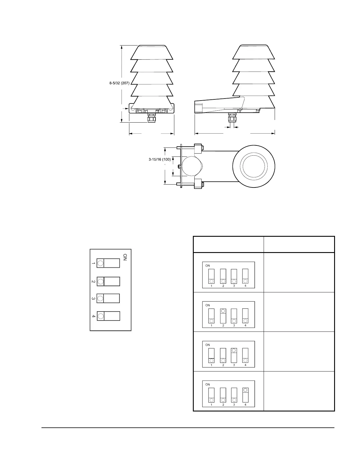
Dimensions
DIP Switch Settings
The DIP switches on the component board control the
humidity output parameter and scaling. Figure 3 shows
the default DIP switch settings.
Change the position of the DIP switches to the desired
setting.
Figure 2: Hx-68P3 Series Outside Humidity and Temperature Transmitter Dimensions, in. (mm)
4-7/8 (122)
10-3/8 (264)
FIG:Di mensions
5/32 to 5/16 (4 to 8) Cable
Diameter 3/32 to 2-11/32 (25 to 60)
Diameter 7/32 (6)
Figure 3: DIP Switch Positions
Non-Metric
Td
h
Tw
Metric
RH
RH
RH
Table 1: DIP Switch Positions for Metric Output
DIP Switch Position Analog Output
Parameter and Scaling
Relative Humidity (RH)
0 to 100%
Temperature (T)
-40 to 60C
Dewpoint (Td)
-40 to 60C
Temperature (T)
-40 to 60C
Enthalpy (h)
-40 to 460kJ/kg
Temperature (T)
-40 to 60C
Wet Bulb Temperature (Tw)
-40 to 60C
Temperature (T)
-40 to 60C
 Loading...