Hx-68P3 Series Outside Humidity and Temperature Transmitters Installation Instructions4
Installing the Conduit Adaptor - Optional
Using the conduit adaptor is optional. If you do not use
the conduit adaptor, proceed to Mounting
.
To install the conduit adaptor, follow these steps.
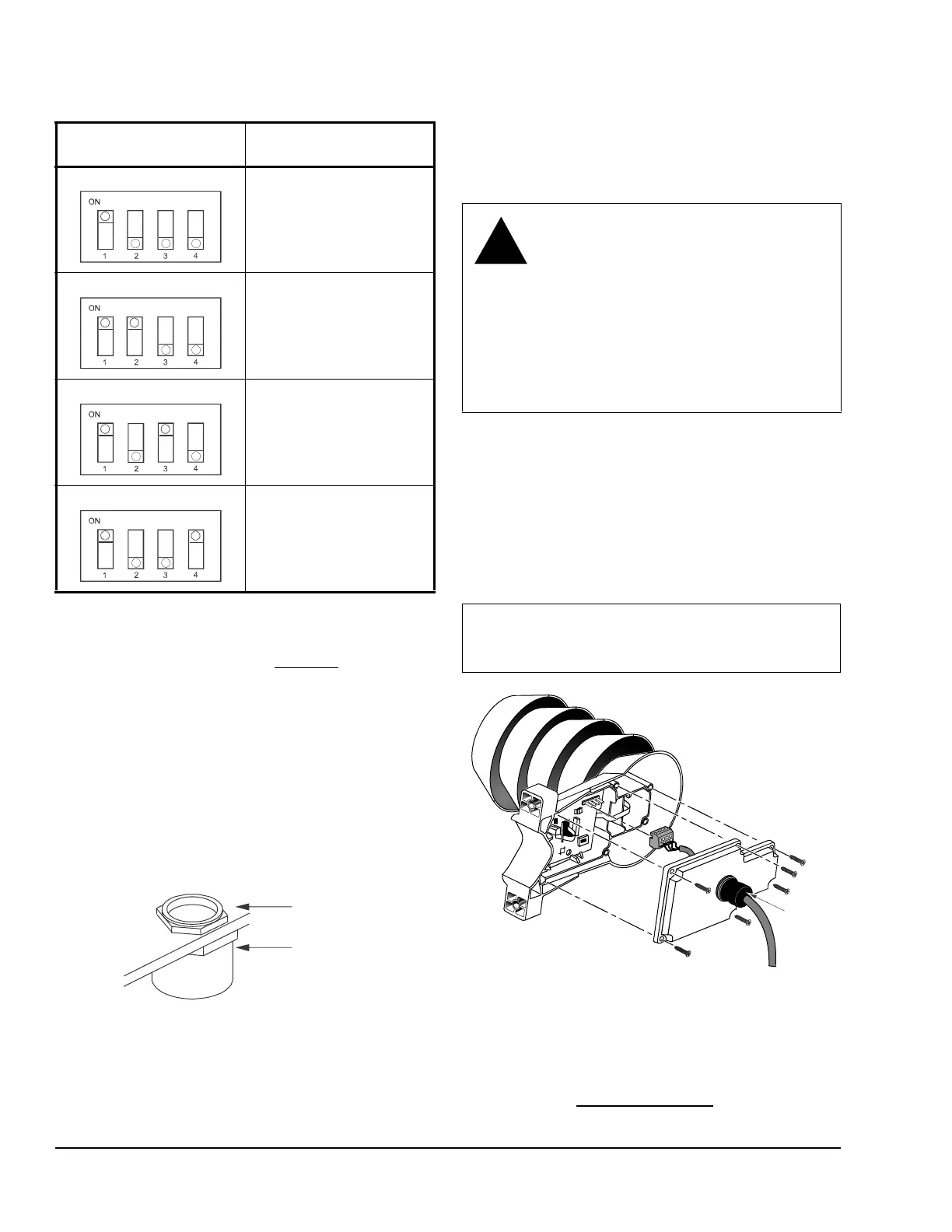
1. Loosen the six captive screws that hold the
transmitter cover in place. See Figure 5.
2. Unscrew the cable gland from the transmitter
cover. See Figure 1 for the location of the cable
gland.
3. Align the nut with the opening inside the transmitter
cover, and insert the adaptor body into the
transmitter conduit opening.
4. Manually tighten the adaptor into the nut, turning in
a clockwise direction.
5. Tighten the adaptor onto the adaptor body, turning
in a clockwise direction.
Mounting
Location Considerations
• Install the transmitter in a place that receives
minimal direct sunlight.
• Avoid placing the transmitter near windows, air
conditioning units, or other heat and moisture
sources such as cooling towers.
• Install the transmitter at least 8 ft (2.5 m) above the
ground.
1. Loosen the six captive screws that hold the
transmitter cover in place.
2. Be sure the DIP switches are set to the desired
setting. See DIP Switch Settings
.
Table 2: DIP Switch Positions for Non-Metric
Output
DIP Switch Position Analog Output
Parameter and Scaling
Relative Humidity (RH)
0 to 100%
Temperature (T)
-40 to 140F
Dewpoint (Td)
-40 to 140F
Temperature (T)
-40 to 140F
Enthalpy (h)
-10 to 190 BTU/lb
Temperature (T)
-40 to 140F
Wet Bulb Temperature (Tw)
-40 to 140F
Temperature (T)
-40 to 140F
Figure 4: Conduit Adaptor
CAUTION: Risk of Electric Shock.
Disconnect the power supply before
making electrical connections to avoid
electric shock.
MISE EN GARDE : Risque de décharge
électrique.
Débrancher l'alimentation avant de
réaliser tout raccordement électrique afin
d'éviter tout risque de décharge
électrique.
IMPORTANT: To minimize the time spent working
on a ladder, prepare the transmitter configuration
and wiring before mounting the transmitter.
Figure 5: Preparing the Transmitter for Mounting
FIG:Termina l
Cable Gland
(Shown)
Screw
Terminal
 Loading...