EasyManua.ls Logo

Johnson Controls (H,Y,C)IDM012B21S - Marking Positions for Suspension Bolts and Piping Connections; Mounting Indoor Unit

Johnson Controls (H,Y,C)IDM012B21S
36 pages
Print Icon
To Next Page IconTo Next Page
To Previous Page IconTo Previous Page
Loading...
P00792Q-rev.2
11
5.3 Mounting Indoor Unit
Hang the indoor unit as shown in Figure 5.3.
Field-Supplied Parts
* Suspension Bolts: 4-M10 or W3/8
* Nut: 8-M10 or W3/8
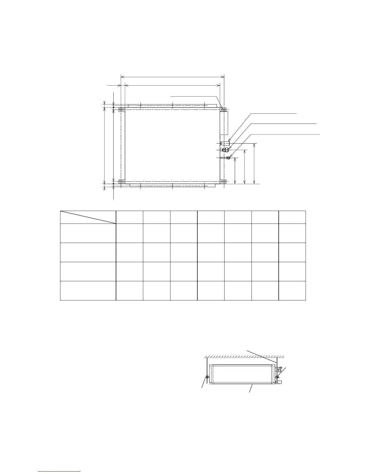
5.2 Marking Positions for Suspension Bolts and Piping Connections
(1) Mark-off the positions for the suspension bolts, refrigerant pipe connections, and drain pipe connection.
(2) Installation dimensions are shown in Figure 5.2.
Figure 5.2 Suspension Bolts
Suspension
Bracket
Suspension Bolts (4-M10 or W3/8)
(Field-Supplied)
False Ceiling Side
Nut & Washer
(8-M10 or W3/8)
Unit
Figure 5.3 Mounting Indoor Unit
1 (25)
7/8 (22)
9/16
(15)
c
f
e
g
1 (25)
7/8 (22)
9/16
(15)
a (for Suspension Bolt)
Drain Pipe Connection
Refrigerant Gas Pipe Connection
Refrigerant Liquid Pipe Connection
Unit: inch (mm)
1
(25)
d
b
4 - 1-9/16 x 1/2 (40 x 12)
(for Suspension Bolt)
(for Suspension Bolt
)
Dimension
Model
a b c d e f g
(H,Y,C)IDM006B21S
(H,Y,C)IDM008B21S
(H,Y,C)IDM012B21S
27-9/16
(700)
25-9/16
(650)
28-3/8
(720)
26-5/8
(676)
12-5/8
(321)
9-11/16
(246)
16-1/16
(408)
(H,Y,C)IDM015B21S
(H,Y,C)IDM018B21S
37-3/8
(950)
35-7/16
(900)
28-3/8
(720)
26-5/8
(676)
12-5/8
(321)
9-11/16
(246)
16-1/16
(408)
(H,Y,C)IDM024B21S
(H,Y,C)IDM030B21S
45-1/4
(1,150)
43-5/16
(1,100)
31-1/2
(800)
29-3/4
(756)
13-9/16
(345)
10-5/8
(270)
16-15/16
(431)
(H,Y,C)IDM036B21S
(H,Y,C)IDM048B21S
57-1/16
(1,450)
55-1/8
(1,400)
31-1/2
(800)
29-3/4
(756)
13-9/16
(345)
10-5/8
(270)
16-15/16
(431)

Related product manuals