EasyManua.ls Logo

Johnson Controls (H,Y,C)IDM012B21S - 7 Drain Piping

Johnson Controls (H,Y,C)IDM012B21S
36 pages
Print Icon
To Next Page IconTo Next Page
To Previous Page IconTo Previous Page
Loading...
18
P00792Q-rev.2
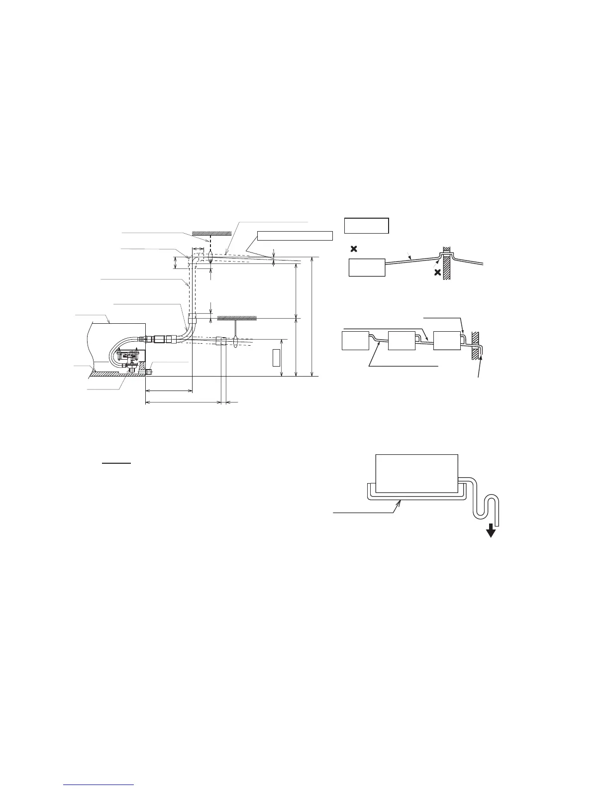
(1) Figure 7.1 shows all drain piping connections.
(2) Prepare a polyvinyl chloride piping with 1-1/4 inches (32mm) outer diameter.
(3) Fasten the tube to the drain hose with the adhesive agent and the eld-supplied clamp.
The drain piping must be performed with a DOWN-SLOPE pitch of 1/25 to 1/100.
(4) Insulate the drain piping after connecting the drain hose.
7. DrainPiping
Perform drain piping work and attach the insulation before attempting any refrigerant piping work.
9-1/4
2-5/16
2-5/16
11
11-7/16
1-15/16 to
22-11/16 (Max.)
14-3/4 to 35-7/16 (Max.
)
(Drain-Up Length)
Drain Piping (PVC Tube)
(Field-Supplied)
1/25 to 1/100 Down-Slope
Unit: inch
Suspension Bracket
(Field-Supplied)
90
o
Elbow Pipe
(Field-Supplied)
Lift Piping for Drain-Up
(PVC Tube)
(Field-Supplied)
Indoor Unit
Drain Pump
Drain
Pan
Rubber Boss
Drain Hose (L: 11-13/16)
(Accessory)
14-15/16 1
7-3/8
Figure 7.1 Drain Piping
Common
Drain Piping
Connection
1/25 to 1/100 Down-Slope
Common Drain Piping
This drain pipe shall be
separating from other pipes.
Incorrect: Upward Slope
Unit
Rising Part
Incorrect
Correct
Indoor Unit
Auxiliary Drain Pan
(Field-Supplied)
To the Atmosphere
Figure 7.2 Auxiliary Drain Pan
NOTE:
If the relative humidity of a parcel of ambient
air exceeds 80%, install a (eld-supplied)
auxiliary drainage pan beneath the indoor unit
as shown in Figure 7.2.

Related product manuals