P00792Q-rev.2
25
1. The DIP switch settings for the outdoor unit should be performed in accordance with the "Installation and
Maintenance Manual" for the outdoor unit.
2. Be aware that communication cable for the wired controller is required in these instances:
a. The following functions are set to the sub unit which is not installed with the wired controller.
● Remote ON/OFF function settings, (No.1, 2, and 3), (External Input / Output Function)
● Power supply ON/OFF functions, (No.1 and 2), (Function Selection)
● Prohibiting the wired controller after manual stoppage (External Input / Output Function)
● Group setting by the centralized controller
b. The combination of twin, triple, or quad is controlled by single wired controller.
c The address for the indoor unit is changed from the wired controller.
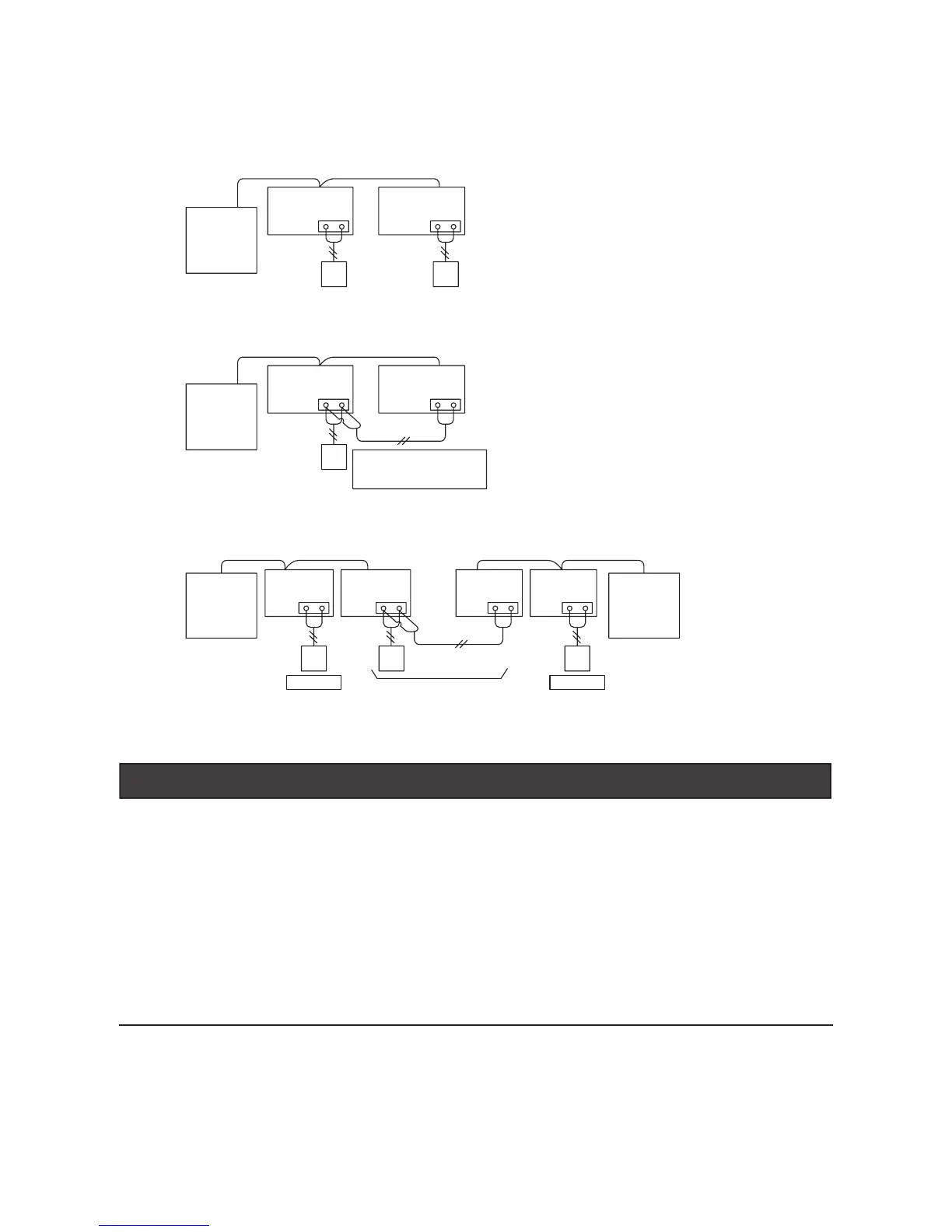
● VRF Systems
(c) Wired Controller Connections between different Refrigerant Cycles
(a) Wired Controllers to each Unit for Individual Operation Setting
(b) Single Wired Controller for Individual Operation Setting
(10) Wired Controller Connection
Outdoor Unit
A B
Outdoor Unit
Indoor UnitIndoor UnitIndoor Unit Indoor Unit
A B
A BA B
Individual
Simultaneous
 Loading...