EasyManua.ls Logo

Johnson Controls ILLUSTRA IQ - User Manual

Johnson Controls ILLUSTRA IQ
2 pages
Print Icon
To Next Page IconTo Next Page
Loading...
Mounting and powering up the camera (continued)
13. Hold the camera dome (6) (Figure1) up to the camera base and
rotate the camera dome to securely lock it to the camera base.
Note:
The camera dome includes a ‘lock’ and ‘unlock’ symbol to
assist with step 13.
14. Connect the AC 24V cable to an AC 24V terminal or
connect the
RJ-45 jack to a PoE compatible network device that supplies
power through the Ethernet cable.
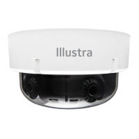
Camera buttons and connections: Figure 2
Figure 2
Security
Quick Start Guide
(A163820G0G_A)
Illustra Flex Gen4 Indoor Dome Camera
(PN’s = IFS02-D12-ATB4, IFS05-D12-ATB4 & IFS08-D13-ATB4)
In the box
x 1 x Indoor dome camera
x 1 x Mounting template sticker
x 1 x Mounting plate
x 2 x 50x4mm tapping screws
x 2 x 40x6mm plastic screw anchors
x 2 x 10x4mm mounting plate screws
x 1 x Printed Quick Start Guide
Installation tools
x 1 x Drill
Camera Parts: Figure 1
Figure 1
Quick reference
x Default IP: 192.168.1.168 (DHCP enabled)
x Default Username / Password: admin
x Power: AC24V / PoE 802.3af
Table 1: Camera part descriptions
Camera Part
Description
1
Mounting Plate
2
Camera base
3
Camera body
4
Camera Lens
5
Camera lens
cover
6
Dome Cover
Mounting and powering up the camera
1. Place the mounting template sticker on the surface that you
want to attach the camera.
2. On the surface drill two Ø 6mm holes and cut out a cable
hole
as per the markings identified on the mounting template sticker.
3. Securely place the two screw anchors into the two Ø 6mm
holes.
Mounting and powering up the camera (continued)
4. Hold the camera dome with one hand and rotate the camera
base to unlock it and remove it from the dome.
Note:
The camera dome includes a ‘lock’ and ‘unlock’ symbol to
assist with step 4.
5. Gently pull up and remove the camera lens cover
(5) (Figure 1)
to easily access the cable connections and buttons.
6. Connect the PoE cable to the PoE slot on the camera or the
AC24V cable to the AC24 connection on the camera.
7. Before you secure the mounting plate (1) (Figure 1) to the
camera base (2) (Figure 1) you must place the cable through
the cable hole on the camera mounting plate.
8. Place the mounting plate onto the camera base so t
hat the three
semicircular swellings on the mounting plate fit correctly into the
three screw holes on the camera base.
9. Place the cable through the cable hole on
the mounting surface.
10. Hold the mounting plate with camera base up to the mounting
template and align two screw holes on the camera base with the
two screw holes on the mounting surface.
11. Insert the two screws into the two holes on the camera base
and securely attach the mounting plate and camera base to the
surface.
12. Insert the camera lens cover (5) (Figure 1) on to the camera
lens.
Table 2: Camera buttons and connections descriptions
Description
AC cable connection
USB cable connection
3
Factory reset
x Hold for 5 seconds for soft reset
x Hold for 20 seconds for hard reset
4
Focus button
x Hold for 3 seconds to run one touch focus
Audio / Alarm cable connection (P/N = IA-CBL-IO-F30)
Micro SD card insert
Ethernet / PoE cable slot
PT01-006062A_FG4-ID-Dome-QSG_A163820G0G_A.en(3-8-23).pdf 1PT01-006062A_FG4-ID-Dome-QSG_A163820G0G_A.en(3-8-23).pdf 1 2023-08-09 10:49:402023-08-09 10:49:40
Question and Answer IconNeed help?

Do you have a question about the Johnson Controls ILLUSTRA IQ and is the answer not in the manual?

Overview

This document describes the Illustra Flex Gen4 Indoor Dome Camera, identified by part numbers IFS02-D12-ATB4, IFS05-D12-ATB4, and IFS08-D13-ATB4. It serves as a quick start guide for installation, configuration, and maintenance.

Function Description

The Illustra Flex Gen4 Indoor Dome Camera is a surveillance device designed for indoor use. It captures video footage and can be integrated into a network for remote monitoring and management. The camera features a 3-axis gimbal for flexible positioning, allowing for pan, tilt, and rotate adjustments to achieve the desired field of view.

Important Technical Specifications

  • Default IP Address: 192.168.1.168 (DHCP enabled)
  • Default Username / Password: admin
  • Power: AC24V / PoE 802.3af
  • Pan Range: 0° to 355°
  • Tilt Range: 0° to 67°
  • Rotate Range: 0° to a minimum of 355°

Usage Features

Installation:

The installation process involves several steps to securely mount and power the camera:

  1. Mounting Template: Begin by placing the provided mounting template sticker on the desired surface.
  2. Drilling: Drill two Ø 6mm holes and cut out a cable hole as indicated by the template.
  3. Screw Anchors: Securely insert the two screw anchors into the drilled holes.
  4. Disassembly: Hold the camera dome and rotate the camera base to unlock and remove it. The dome includes 'lock' and 'unlock' symbols for guidance.
  5. Lens Cover Removal: Gently pull up and remove the camera lens cover (part 5 in Figure 1) to access cable connections and buttons.
  6. Cable Routing: Before securing the mounting plate (part 1 in Figure 1) to the camera base (part 2 in Figure 1), route the cable through the cable hole on the mounting plate.
  7. Mounting Plate Alignment: Place the mounting plate onto the camera base, ensuring the three semicircular swellings on the mounting plate align with the three screw holes on the camera base.
  8. Surface Cable Routing: Route the cable through the cable hole on the mounting surface.
  9. Mounting Plate and Camera Base Attachment: Align two screw holes on the camera base with the two screw holes on the mounting surface, then insert the two screws to securely attach the mounting plate and camera base to the surface.
  10. Lens Cover Reinstallation: Insert the camera lens cover onto the camera lens.
  11. Dome Reinstallation: Hold the camera dome (part 6 in Figure 1) up to the camera base and rotate it to securely lock it. The dome includes 'lock' and 'unlock' symbols for guidance.
  12. Power Connection: Connect the AC 24V cable to an AC 24V terminal or connect the RJ-45 jack to a PoE compatible network device that supplies power through the Ethernet cable.

Camera Components (Figure 1):

  • 1. Mounting Plate: Used for securing the camera to a surface.
  • 2. Camera Base: The main structural component that houses the camera body.
  • 3. Camera Body: Contains the camera's internal electronics and imaging sensor.
  • 4. Camera Lens: The optical component responsible for capturing images.
  • 5. Camera Lens Cover: Protects the camera lens.
  • 6. Dome Cover: The outer protective casing of the camera.

Buttons and Connections (Figure 2):

  • 1. AC cable connection: For connecting to an AC 24V power source.
  • 2. USB cable connection: Used for connecting to a USB cable for configuration and maintenance.
  • 3. Factory reset button:
    • Hold for 5 seconds for a soft reset.
    • Hold for 20 seconds for a hard reset.
  • 4. Focus button: Hold for 3 seconds to run a one-touch focus.
  • 5. Audio / Alarm cable connection: For connecting audio and alarm input/output (P/N = IA-CBL-IO-F30).
  • 6. Micro SD card insert: For local storage of video footage.
  • 7. Ethernet / PoE cable slot: For network connection and Power over Ethernet.

Adjusting Camera Position (Figure 3):

The camera's 3-axis gimbal allows for precise adjustments:

  • Pan: The camera can pan from 0° to 355°.
  • Tilt: The camera can tilt from 0° to 67°.
  • Rotate: The camera can rotate from 0° to a minimum of 355°.

Dome Cover Management:

  • Removing the dome: Hold the camera dome (part 6) with one hand and rotate the camera base (part 2) to unlock it and remove it.
  • Installing the dome: Hold the camera dome (part 6) up to the camera base (part 2) and rotate it to securely lock it.

Applicable Bubble Accessories (Table 4):

  • IFID-BSMKBBL-04: Illustra Flex Smoked Bubble for Indoor Domes, Black Trim.
  • IFID-WCLRBBL-04: Illustra Flex Clear Bubble for Indoor Domes, White Trim.
  • IFID-WSMKBBL-04: Illustra Flex Smoked Bubble for Indoor Domes, White Trim.

Mounting Plate Symbols and Descriptions (Table 3):

  • A (Single Gang Box): Attach the plate to a North American single gang electrical box.
  • B (Octagon Box): Attach the plate to a North American octagon electrical box.
  • C (Double Gang Box): Attach the plate to a North American double gang electrical box.
  • D (4S Junction Box): Attach the plate to a North American 4 inch square electrical box.

Maintenance Features

  • Soft Reset: Hold the factory reset button for 5 seconds.
  • Hard Reset: Hold the factory reset button for 20 seconds.
  • One-Touch Focus: Hold the focus button for 3 seconds.
  • Firmware Updates: The Illustra Tools application (available via QR codes for iOS and Android) can be used to install, configure, and maintain cameras, including potential firmware updates.

Important Warnings:

  • This product is intended for professional installation and requires adherence to local wiring regulations.
  • To meet EU security immunity requirements, the product should be used with an Uninterruptible Power Supply (UPS) for the mains input.
  • The product must be powered by a Limited Power Supply (LPS) sized according to the product rating label.
  • The LAN symbol on the unit indicates it is not intended for connection to a public network or a LAN from a different building.
  • Mounting, including climbing ladders and handling communications/power, can be hazardous. Only skilled persons should install this device.
  • This camera can be mounted at a distance greater than 2 meters (6.6 feet) from the floor. Ensure the camera is securely mounted to prevent injury from falling.

Johnson Controls ILLUSTRA IQ Specifications

General IconGeneral
BrandJohnson Controls
ModelILLUSTRA IQ
CategorySecurity Camera
LanguageEnglish

Related product manuals