Table 7: SA/FC bus device address descriptions
Device
address
Use on description
0
(Switch 128
Off)
Reserved for FC Bus Supervisory Controller (not for
use on controllers).
1 to 3
(Switch 128
Off)
Reserved for peripheral devices (not for use on
controllers).
4 to 127
(Switch 128
Off)
Used for MS/TP master devices (controllers) that
are hardwired to an SA Bus or FC Bus.
0 to 3
(Switch 128
ON)
Reserved addresses for wired subordinate devices
(not for use on controllers).
Note: Metasys field controllers ship with
switch 128 ON and the remaining address
switches off rendering the controllers wired
subordinate devices, which do not operate on
MS/TP buses.
4 to 127
(Switch 128
ON)
Valid for MS/TP Master controllers on wireless FC
Buses only.
Note: Do not connect a controller with switch
128 ON to an active (hard-wired) SA or
FC bus. When a controller with switch 128
ON and a device address from 4 to 127 is
connected to a wired field bus, the entire
field bus is rendered inoperable until the
controller is disconnected or switch 128 is set
to off.
Removing the Controller cover
Important: Electrostatic discharge can damage
controller components. Use proper electrostatic
discharge precautions during installation, setup, and
servicing to avoid damaging the controller.
Important: Disconnect all the power sources to
the controller before removing cover and changing
the position of any jumper or the EOL switch on
the controller. Failure to disconnect power before
changing a jumper or EOL switch position can result
in damage to the controller and void any warranties.
The controller cover is held in place by four plastic
latches that extend from the base and snap into
slots on the inside of the housing cover.
To remove the controller cover:
1. Place your fingernails under the two cover lift tabs
(Figure 1) on the sides of the housing cover and
gently pry the top of the cover away from the base to
release the cover from the two upper latches.
2. Pivot the top of the cover further to release it from
the lower two latches.
3. Replace the cover by placing it squarely over the
base, and then gently and evenly push the cover
on to the latches until they snap into the latched
position.
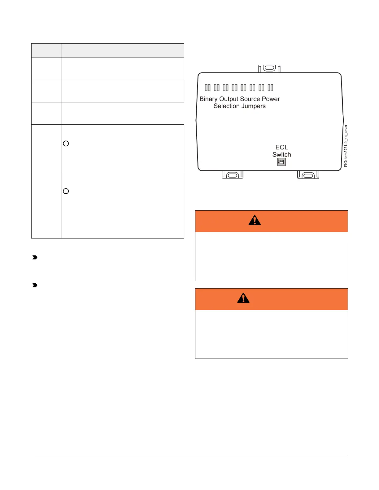
EOL switch location
Figure 10: IOM3731 with cover removed showing EOL
switch location
Binary Output (BO) source power
selection jumpers
Warning
Risk of Electric Shock
Disconnect supply power to the controller before at-
tempting to adjust the Binary Output Source Power
Selection Jumpers. Failure to disconnect the supply
power may result in electric shock.
Avertissement
Mise En Garde: Risque de décharge électrique
Débrancher l'alimentation de l'controller avant tout
réglage du Binary Output Source Power Selection
Jumpers. Le non-respect de cette précaution risque
de provoquer une décharge électrique.
The BO source power selection jumpers determine
whether a BO provides internal power (sourced from the
controller) to the output load (INT position) or requires
an external power source (EXT position) for the output
load. Figure 11 shows an example of a controller BOs and
the associated power selection jumpers to the right of the
BOs terminal block.
IOM3731 Input/Output Module Installation Guide 11