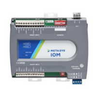
Figure 1: IOM3731 physical features
Table 1: IOM3731 physical features callouts and
descriptions
Callo
ut
Physical feature: description and references
1 Binary Outputs (BOs) Terminal Block (see Table 2)
2 Mounting Clip
3
Device Address DIP Switch Block (see Setting the device
addresses)
4
24 VAC, Class 2 Supply Power Terminal Block (see Supply
power terminal block)
5 Cover Lift Tab (see Removing the Controller cover)
6
Sensor Actuator (SA) Bus / Field Controller (FC) Bus
Terminal Block (see SA/FC bus terminal block)
7 Binary Inputs (BIs) Terminal Block (see Table 2)
8 LED Status Indicators
9
Sensor Actuator (SA) Bus or Field Controller (FC) Bus Port
(RJ-12 6-pin Modular Jack) (see SA/FC bus port)
Mounting
Observe these guidelines when mounting a field
controller:
• Ensure the mounting surface can support the
controller, DIN rail, and any user-supplied enclosure.
• Mount the controller horizontally on 35 mm DIN rail
whenever possible.
• Mount the controller in the proper mounting position
(Figure 2).
• Mount the controller on a hard, even surface whenever
possible in wall-mount applications.
• Use shims or washers to mount the controller securely
and evenly on the mounting surface.
• Mount the controller in an area free of corrosive vapors
and observe the Ambient Conditions requirements in
Table 9.
• Provide for sufficient space around the controller for
cable and wire connections for easy cover removal
and good ventilation through the controller (50 mm
[2 in.] minimum on the top, bottom, and front of the
controller).
• Do not mount the controller on surfaces prone to
vibration, such as duct work.
• Do not mount the controller in areas where
electromagnetic emissions from other devices or wiring
can interfere with controller communication.
Observe these additional guidelines when mounting a
controller in a panel or enclosure:
• Mount the controller so that the enclosure walls do
not obstruct cover removal or ventilation through the
controller.
• Mount the controller so that the power transformer
and other devices do not radiate excessive heat to the
controller.
• Do not install the controller in an airtight enclosure.
IOM3731 Input/Output Module Installation Guide2