Do you have a question about the Johnson Controls IOM3731 and is the answer not in the manual?
Module part of Metasys system, expands I/O points for HVAC equipment.
Digital apparatus meets Canadian Interference-Causing Equipment Regulations.
FCC compliance for Class A digital device, radio frequency energy.
Observe guidelines for safe and proper controller installation.
Lists components included with the controller, like terminal blocks and instructions.
Lists required fasteners, DIN rail, and screwdriver for installation.
Guidelines for mounting the controller securely and in appropriate locations.
Guidelines for mounting in panels or enclosures to ensure ventilation and prevent heat issues.
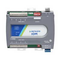
Identifies physical features of the IOM3731 controller with descriptions and references.
Procedures for mounting the controller horizontally on a 35 mm DIN rail.
Procedures for mounting the controller directly on a wall or flat vertical surface.
Warning about disconnecting power before making electrical connections.
Cautionary note about checking wiring connections before applying power.
Guidelines for preventing damage to controller components from static discharge.
Describes location and function of input/output terminal blocks.
Details on the removable 4-terminal plug for SA/FC bus connection.
Wiring instructions for connecting to an FC bus segment.
Wiring instructions for connecting to an SA bus segment.
Description of the RJ-12 port for SA/FC bus and wireless connections.
Details on wiring the 24 VAC supply power to the controller.
Configuration for using the controller with a ZFR/ZFR Pro Wireless Field Bus Router.
Guidelines for functions, ratings, requirements for controller input/output terminals.
Guidelines for running low-voltage wiring, cable types, and cable length considerations.
Details on terminal blocks, functions, ratings, and requirements for I/O.
Guidelines for cable length based on wire size for low-voltage inputs and outputs.
Estimating max cable length relative to wire size and load current for inputs/outputs.
Guidelines for SA/FC bus and 24 VAC supply power wiring.
Ratings and requirements for communications bus and power supply terminal blocks.
Explanation of controller status LED indicators and their meanings.
Using status LEDs to troubleshoot controller issues.
Details on LED states for SA/FC BUS and EOL indicators.
Diagrams illustrating wiring for different types of inputs and outputs.
Procedures for setting unique device addresses using DIP switches.
Instructions for setting switch 128 for wireless FC bus applications.
Table detailing device address use based on switch 128 settings.
Step-by-step instructions for safely removing the controller cover.
Explanation of jumpers determining internal vs. external power for BOs.
Instructions on setting the EOL switch to ON or Off for bus termination.
List of ordering codes for related accessories like transformers and displays.
Detailed technical specifications including voltage, power, ambient conditions, and processor.
Dimensions, weight, and compliance details for the controller.
Information on the limited warranty coverage for the product.
Contact information for different regions (APAC, Europe, NA/SA).
| Model | IOM3731 |
|---|---|
| Type | Input/Output Module |
| Communication Protocol | BACnet MS/TP |
| Number of Outputs | 8 |
| Mounting Type | DIN Rail |
| Output Type | Binary |
| Enclosure Material | Plastic |
| Number of Binary Outputs | 8 |
| Input Voltage | 24 VAC |
| Input Type | Universal |