Table 5: Status LEDs and descriptions of LED states
LED label LED color Normal LED state Description of LED states
SA/FC BUS Green Blink - 2 Hz
Blink - 2 Hz = Data Transmission (normal communication)
Off Steady = No Data Transmission (N/A - auto baud not supported)
On Steady = Communication lost, waiting to join communication ring
EOL Amber
Off (Except on
terminating
devices)
On Steady = EOL switch in ON position
Off Steady = EOL switch in Off position
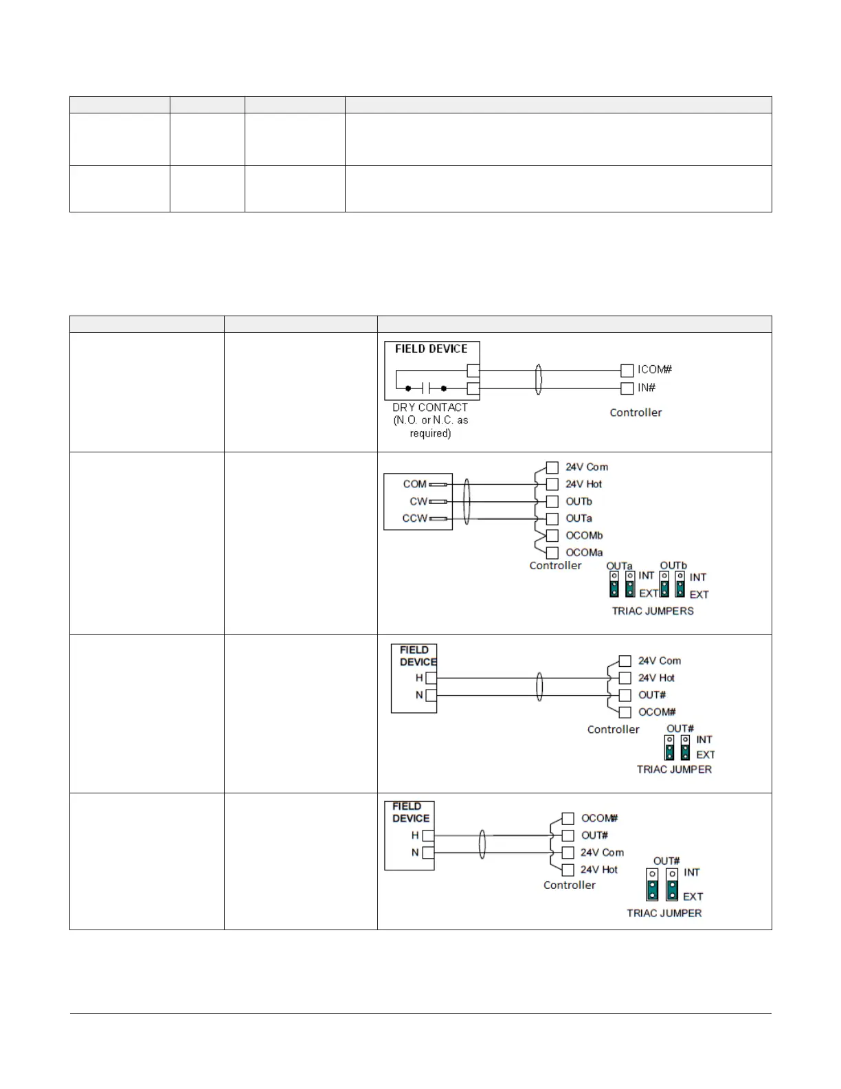
Termination details
A set of Johnson Controls termination diagrams provides
details for wiring inputs and outputs to the controllers.
See the figures in this section for the applicable
termination diagrams.
Table 6: Termination details
Type of field device Type of Input/Output Termination diagrams
Dry Contact (Binary Input) BI
Incremental Control to
Actuator (Switch Low,
Externally Sourced)
BO
24 VAC Binary Output
(Switch Low, Externally
Sourced)
BO
24 VAC Binary Output
(Switch High, Externally
Sourced)
BO
IOM3731 Input/Output Module Installation Guide 9