CAUTION
Risk of Personal Injury and Property Damage
Do not apply power to the system before checking all
wiring connections. Short circuited or improperly con-
nected wires may result in permanent damage to the
equipment.
ATTENTION
Mise En Garde: Risque de dégâts matériels
Ne pas mettre le système sous tension avant d'avoir
vérifié tous les raccords de câblage. Des fils for-
mant un court-circuit ou connectés de façon incor-
recte risquent d'endommager irrémédiablement
l'équipement.
Important: Do not exceed the controller electrical
ratings. Exceeding controller electrical ratings can
result in permanent damage to the controller and
void any warranty.
Important: Use copper conductors only. Make
all wiring in accordance with local, national, and
regional regulations.
Important: Electrostatic discharge can damage
controller components. Use proper electrostatic
discharge precautions during installation, setup, and
servicing to avoid damaging the controller.
For detailed information on configuring and wiring
an MS/TP Bus, FC bus, and SA bus, refer to the MS/TP
Communications Bus Technical Bulletin (LIT-12011034).
Terminal blocks and bus ports
See Figure 1 for terminal block and bus port locations
on the IOM controller. Observe the following guidelines
when wiring an IOM controller.
Input and Output terminal blocks
All of the input terminal blocks are mounted on the
bottom of the controller and the output terminal blocks
are mounted on the top of the controller. See Table
2 for more information about I/O terminal functions,
requirements, and ratings.
SA/FC bus terminal block
An IOM can be connected to a SA bus or a FC bus, but not
to both buses simultaneously. The SA/FC bus terminal
block is a removable, 4-terminal plug that fits into a
board-mounted jack.
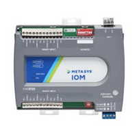
When connecting the IOM to an FC bus, wire the bus
terminal block plugs on the controller, and the other
controllers in a daisy-chain configuration using 3-wire
twisted, shielded cable as shown in Figure 4. See Table 4
for more information.
Figure 4: FC bus terminal block wiring
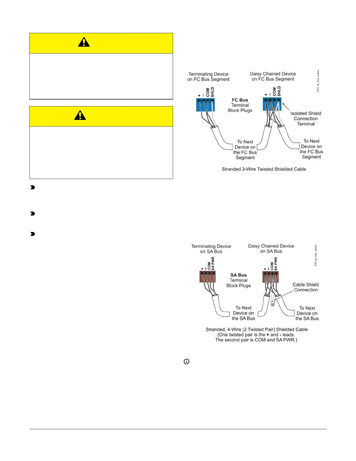
When connecting the IOM to an SA bus, wire the bus
terminal block plugs on the controller and other SA
bus devices in a daisy-chain configuration using 4-wire
twisted, shielded cable as shown in Figure 5. See Table 3
for more information.
Figure 5: SA bus terminal block wiring
Note: The SA PWR/SHLD terminal does not supply 15
VDC. The SA PWR/SHLD terminal is isolated and can
be used to connect (daisy chain) the 15 VDC power
leads on the SA bus (Figure 5) or the cable shields
on the FC bus (Figure 4). The SA bus supervisor (FAC,
FEC, or VMA) supplies 15 VDC to devices on the SA
bus requiring power.
IOM3731 Input/Output Module Installation Guide4