JC-460-000 4 I56-3750-001
©2008 Johnson Controls, Inc.
Before InstallIng
This information is included as a quick reference installation guide. Refer to
the control panel installation manual for detailed system information. If the
modules will be installed in an existing operational system, inform the opera-
tor and local authority that the system will be temporarily out of service. Dis-
connect power to the control panel before installing the modules.
NOTICE: This manual should be left with the owner/user of this equipment.
general DescrIptIon
M300CJ Supervised Control Modules are intended for use in intelligent, two-
wire systems, where the individual address of each module is selected us-
ing the built-in rotary switches. This module is used to switch an external
power supply, which can be a DC power supply or an audio amplifier (up
to 80 VRMS), to notification appliances. It also supervises the wiring to the
connected loads and reports their status to the panel as NORMAL, OPEN,
or SHORT CIRCUIT. The M300CJ has two pairs of output termination points
available for fault-tolerant wiring and a panel-controlled LED indicator. This
module can be used to replace a M510CJ module that has been configured for
supervised wiring operation.
compatIBIlIty requIrements
To ensure proper operation, this module shall be connected to a compatible
system control panel (list available from Johnson Controls).
mountIng
The M300CJ mounts directly to 4-inch square electrical boxes (see Figure 2A).
The box must have a minimum depth of 2
1
⁄8 inches. Surface mounted electri-
cal boxes (SMB500) are available from Johnson Controls.
WIrIng
NOTE: All wiring must conform to applicable local codes, ordinances, and
regulations. When using control modules in nonpower limited applications,
the CB500 Module Barrier must be used to meet UL requirements for the sepa-
ration of power-limited and nonpower-limited terminals and wiring. The bar-
rier must be inserted into a 4˝×4˝×2
1
⁄8˝ junction box, and the control module
must be placed into the barrier and attached to the junction box (Figure 2A).
The power-limited wiring must be placed into the isolated quadrant of the
module barrier (Figure 2B).
1. Install module wiring in accordance with the job drawings and appropri-
ate wiring diagrams.
2. Set the address on the module per job drawings.
3. Secure module to electrical box, supplied by installer (see Figure 2A).
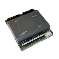
IMPORTANT: When using the M300CJ for fire fighter telephone applications,
remove Jumper (J1) and discard. The Jumper is located on the back as shown
in Figure 1B. The module does not provide ring back when used as a fire-
fighter telephone circuit.
specIfIcatIons
Normal Operating Voltage: 15 to 32 VDC
Maximum Current Draw: 6.5 mA (LED on)
Average Operating Current: 375µA (LED Flashing, Group Poll); 350µA (LED Flashing, Direct Poll); 485µA Max. (LED Flashing, NAC Shorted)
Maximum NAC Line Loss: 4 VDC
External Supply Voltage (between Terminals T3 and T4)
Maximum (NAC): Regulated 24 VDC
Maximum (Speakers): 70.7Vrms, 50W
Drain on External Supply: 1.7 mA Max. using 24 VDC supply; 2.2 mA max. using 80Vrms supply
Maximum NAC Current Ratings: For Class B Wiring System, 3A; For Class A Wiring System, 2A
Temperature Range: 32°F to 120°F (0°C to 49°C)
Humidity: 10% to 93% Non-condensing
Dimensions: 4
1
⁄2˝ H x 4˝ W x 1
1
⁄4˝ D (Mounts to a 4˝ square by 2
1
⁄8˝ deep box.)
Accessories: SMB500 Electrical Box; CB500 Barrier
m300cJ superVIseD control moDule
JC-460-000 1 I56-3750-001
I56-3750-001
507 E. Michigan Street
Milwaukee, WI 53201
InstallatIon anD maIntenance InstructIons
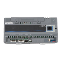
fIgure 1a: fIgure 1B. Jumper locatIon:
C1059-00 C0910-00
fIgure 2a. moDule mountIng fIgure 2B:
WIth BarrIer:
C1070-00