Engine Commissioning for Modbus Vendor Integration
Application Note (LIT-12013150) for additional information.)
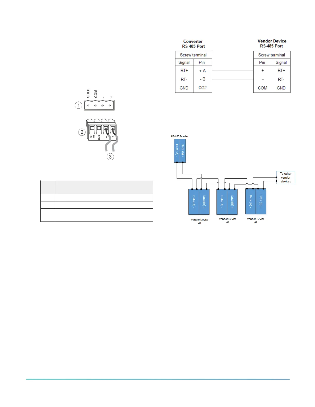
1. For a Modbus RTU device that requires an RS-485
connection, terminate the 2-wire bus cable from
the Modbus device to one of the removable 4-
terminal blue plugs on the network engine, labeled
FC-A and FC-B (Figure 10).
Figure 10: FC Bus terminal block and wiring
connections for Modbus
Table 5: FC Bus terminal block wiring for
Modbus
Callou
t
Description
1 FC Bus terminal block
2 FC Bus terminal block plug
3 Terminating wires for Modbus (2-wire cable
shown)
2. For a Modbus RTU device that requires an RS232C
serial connection, use a cable to connect the
converter to either the RS232C A or RS232C B serial
port on the network engine. The maximum cable
length between devices connected though an
RS-232 line depends on the baud rate used. In
general, the cable should not exceed 15 meters for
9600 baud.
3. Wire from the RS-485 terminal on the converter to
the RS-485 port on the vendor device (Figure 11).
The RS-485 bus is a two-wire network.
a. Connect the converter's + A terminal to the
device's + (or A) terminal.
b. Connect the converter's - B terminal to the
device's - (or B) terminal.
Figure 11: Connection between converter and device
4. To add additional vendor devices, wire from one
device to the next in a daisy chain configuration.
The completed wiring should look similar to Figure
12.
Figure 12: Modbus RTU wiring detail overview
Connecting M-Bus devices
About this task:
The network engine connects to the M-Bus network
devices by using the M-Bus Level Converter. Two
components are needed: serial connection cable (INT-DX-
KAB01) and the M-Bus Level Converter. (After installation
and wiring are complete, refer to the Network Engine
Commissioning for M-Bus Vendor Integration Application
Note (LIT-12013149) for additional information.)
1. Connect the RS-232 cable from either RS232C
serial port on the network engine to the RS-232
connection on the M-Bus Level Converter using
cable INT-DX-KAB01 (Figure 13). Wire to terminals
GND, RxD, and TxD (Table 6).
2. Wire from the M- and M+ terminals on the level
converter to the meters using a free (star, ring,
or bus) topology, preferably bus. Specific cabling
can vary depending on the topology and site. See
Wiring considerations and guidelines for network
integrations.
NAE55 Installation Guide 7

 Loading...

