EasyManuals Logo

Johnson Controls MR4PMUHV User Manual

Johnson Controls MR4PMUHV
13 pages
To Next Page IconTo Next Page
To Previous Page IconTo Previous Page
Page #10 background imageLoading...
Page #10 background image
10 MR4PMUHV Electronic Temperature/Defrost Control with Relay Pack Product/Technical Bulletin
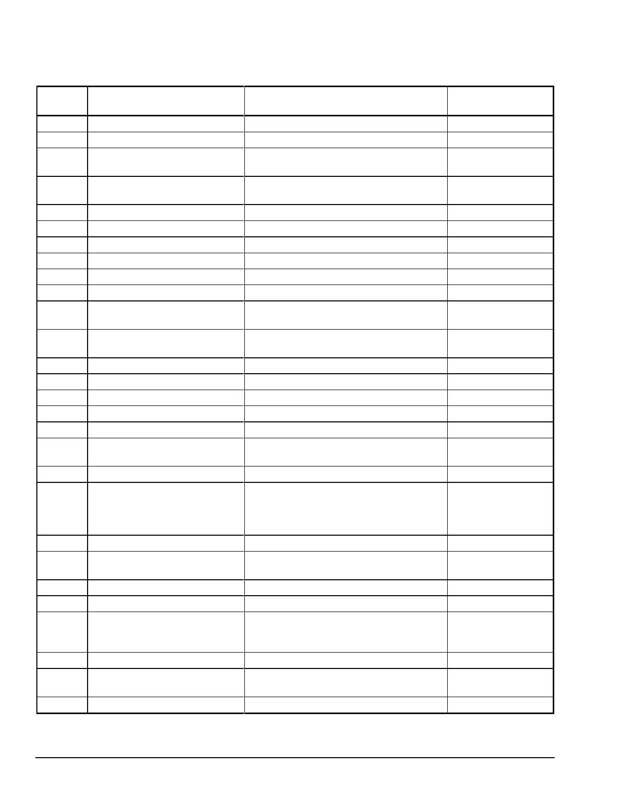
Table 4: Function Settings in Order of Programming in Control Module
Display
Code
Function
Useable Setting Range and Unit Value
Factory-Set Values
(None)
Setpoint
-40 to 99°F (-40 to 80°C)
HY
Differential
1 to 9F° (1 to 9C°)
5 (F°)
LL
Low Setpoint Stop
-40°F (-40°C) to
High Setpoint Stop
-25 (°F)
HL
High Setpoint Stop
Low Setpoint Stop to
99°F (80°C)
40 (°F)
CC
Cycle Delay
0 to 9 minutes
1 (minutes)
Co
Deep Freezing Time
0 to 99 minutes
60 (minutes)
AH
High Temperature Alarm
0 to 50F° (0 to 50C°)
10 (F°)
AL
Low Temperature Alarm
-50 to 0F° (-50 to 0C°)
-10 (F°)
Ad
Alarm Differential
1 to 9F° (1 to 9C°)
5 (F°)
At
Alarm Time Delay
0 to 99 minutes
3 (minutes)
dF
Defrost Mode
0 = electric defrost
1 = hot gas defrost
0 (electric defrost)
dE
Defrost Termination Mode
0 = time-based
1 = temperature-based
1 (temperature-based)
dt
Defrost Termination Temperature
32 to 68°F (0 to 20°C)
55 (°F)
di
Defrost Interval
1 to 99 hours
7 (hours)
dd
Maximum Defrost Duration
0 to 99 minutes
45 (minutes)
dC
Dripping Time
0 to 99 minutes
5 (minutes)
dU
First Defrost Delay
OF, 0 to 99 minutes
OF (Off)
dP
Display During Defrost
0 = last main sensor reading
1 = main setpoint
0 (last main sensor
reading)
dr
Display Delay After Defrost
1 to 99 minutes
20 (minutes)
iF
Binary Input Mode
0 = no response
1 = compressor off, alarm on
2 = alarm on
3 = evap. fan off, alarm on
0 (no response)
id
Binary Input Time Delay
0 to 99 minutes
0 (minutes)
FF
Fan Operating Mode
0 = parallel with compressor
1 = always on
0 (parallel with
compressor)
Fd
Fan Startup Delay
0 to 99 minutes
5 (minutes)
Fr
Fan Start Temperature
-22 to 41°F (-30 to 5°C)
40 (°F)
SF
Sensor Failure Operation
0 = compressor on
1 = compressor off
2 = based on last four cycles
2 (based on last four
cycles)
So
Temperature Sensor Offset
-20 to 20F° (-20 to 20C°)
0 (F°)
Un
Temperature Units Used
0 = °C
1 = °F
1 (°F)
PU
Display Refresh Rate
1 to 99 seconds
1 (second)

Questions and Answers:

Question and Answer IconNeed help?

Do you have a question about the Johnson Controls MR4PMUHV and is the answer not in the manual?

Johnson Controls MR4PMUHV Specifications

MR4PMUHV-12C

Power IconPower
frequency60 Hz
power consumption5VA @240, 5VA @120
Operating Environment IconOperating Environment
ambient operating conditions+14 to +111°F (-10 to +44°C); derate 6.25% per 1°C from 45°C to 60°C; 0 to 95 % RH (non-condensing)
ambient storage conditions-22 to +176°F (-30 to +80°C); 0 to 95 % RH (non-condensing)
accuracy± 1.8F° ( ± 1C°)
Weight and Dimensions IconWeight and Dimensions
dimensions7.94 x 3.6 x 2.4 in. (202 x 92 x 61 mm)
shipping weight2.9 lb (1320g)
A99 sensor cable length6.6 ft (2m)

MR4PM12C-12C

Operating Environment IconOperating Environment
ambient operating conditions+14 to +140°F (-10 to +60°C); 0 to 95 % RH (non-condensing)
ambient storage conditions-22 to +176°F (-30 to +80°C); 0 to 95 % RH (non-condensing)
accuracy± 1.8F° ( ± 1C°)

RP4MRUHV-1C

Operating Environment IconOperating Environment
ambient operating conditions-40 to +111°F (-40 to +44°C); derate 6.25% per 1°C from 45°C to 60°C; 0 to 95 % RH (non-condensing)
ambient storage conditions-40 to +185°F (-40 to +85°C); 0 to 95 % RH (non-condensing)
accuracy± 1.8F° ( ± 1C°)