MR4PMUHV Electronic Temperature/Defrost Control with Relay Pack Product/Technical Bulletin 3
Binary Input Response
Binary Input Function allows the user to select
which output relays respond to a binary input
(switch) if the binary input contacts are open for a
time (in minutes) longer than the Binary Input Time
Delay.
Additional Features
The MR4PMUHV control uses several other settings
to control specific features:
Keyboard locking disables/enables change of
the setpoint and other functions, reducing
accidental or unauthorized changes of the
control settings.
Self-Test Procedure initiates a test cycle of all
outputs and tests all Light-Emitting Diodes
(LEDs). See Initiating a Manual Self-Test.
Manual Deep Freeze Cycle manually initiates a
deep freeze cycle, which is useful when loading
a cold room or a display cabinet. See Initiating a
Manual Deep Freeze Cycle.
Manual Defrost interrupts normal control
operation and initiates an immediate defrost
cycle. See Initiating a Manual Defrost Cycle.
For additional information about control functions
and how to program them, see Programming the
Control and Control Functions.
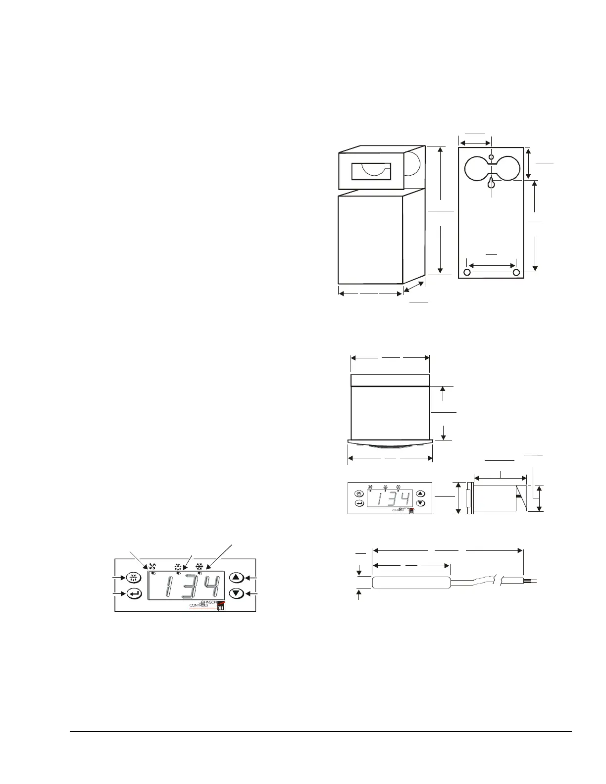
Control Module Front Panel
The control module has an LED display and buttons
for entering programming information and activating
various features.
The display has three LED digits. It displays a
temperature range from -40 to 176°F (-40 to 80°C)
in increments of 1F° or C°. The display also features
three status LEDs.
Manual
Defrost
Button
Enter
Button
Evaporator Fan
Status LED
Defrost
Status LED
Compressor Output
Status LED
Up
Button
Down
Button
Figure 2: Control Module Front Panel
Installation
See Mounting and Wiring for installation information.
Dimensions
3-5/8
(92)
2-3/8
(61)
7-15/16
(202)
1-3/4
(44)
1-5/8
(42)
6
(152)
3
(76)
Figure 3: Relay Pack with Mounting Bracket
Dimensions, in. (mm)
2-5/16
(58)
2-3/4
(70)
3
(75)
1-3/8
(35)
1-1/8
(28)
2-11/16
(68)
Figure 4: Control Module Dimensions, in. (mm)
Figure 5: A99BB-200C Sensor Dimensions, in. (mm)