8 MR4PMUHV Electronic Temperature/Defrost Control with Relay Pack Product/Technical Bulletin
Control Functions
Temperature Management Functions
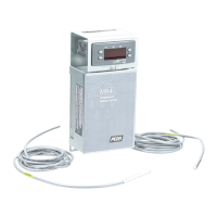
Setpoint is the primary temperature setting (°F or °C)
programmed by the user. When the sensed
temperature drops to the Setpoint value, the Normally
Open (N.O.) compressor relay contacts open, ending
the On cycle. See Figure 13.
HY Differential is the difference (F° or C°) between
Setpoint and the temperature at which the compressor
relay contacts close, initiating the next On cycle. See
Figure 13.
Setpoint
Temperature
Rise
Differential
N.O. Contacts
Close
N.O. Contacts
Open
Figure 13: Setpoint and Differential
HL, LL High and Low Setpoint Stops are
temperature values (°F or °C) that define high or low
boundaries of Setpoint adjustment. Setpoint Stops
deter unauthorized or accidental overadjustment of the
Setpoint.
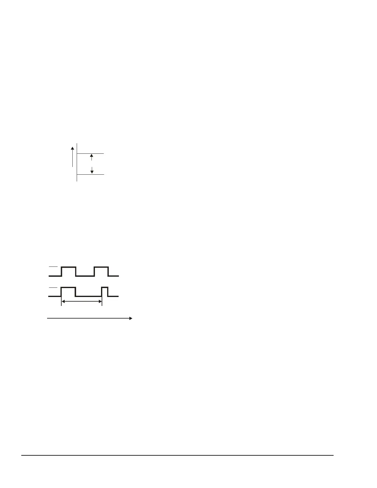
CC Cycle Delay establishes the minimum time
(minutes) between subsequent On cycles of the
compressor. See Figure 14.
Load Demand
Output Status
Cycle Delay
On
On
Off
Off
Time
Figure 14: Cycle Delay
Co Deep Freezing Time overrides Setpoint
temperature control and closes the compressor relay
contacts for a user-defined time (minutes). Typically,
this function is used to run the compressor
continuously during periods of high refrigeration load
to bring the sensed temperature below Setpoint and
deep-freeze the product.
SF Sensor Failure Operation establishes how the
compressor relay contacts operate in the event of a
sensor-related failure. The compressor can remain Off,
remain On, or cycle based on the average of the last
four cycles.
In determining the average of the last four cycles, the
control ignores deep freezing cycles, defrost cycles,
and the first cycle after a deep freeze cycle or a
defrost cycle.
So Temperature Sensor Offset provides
compensation for temperature differences between
actual and displayed temperature, such as when using
long sensor leads. See Table 1 to determine the
temperature value to compensate for long sensor lead
extensions.
Un Temperature Units Used allows selection of
Fahrenheit or Celsius temperature scale.
PU Display Refresh Rate establishes the time delay
(seconds) between updates of the temperature
display.
Alarm Management Functions
AH High Temperature Alarm establishes the
temperature relative to Setpoint (F° or C°) at which the
control goes into a high temperature alarm condition.
(The temperature value is added to the Setpoint.)
AL Low Temperature Alarm establishes the
temperature relative to Setpoint (F° or C°) at which the
control goes into a low temperature alarm condition.
(The temperature value is subtracted from the
Setpoint.)
AH, AL High and Low Temperature Alarms are
disabled during defrost and for 20 minutes after the
defrost cycle. These alarms are also disabled for
20 minutes after startup.
Ad Alarm Differential establishes the difference
(F° or C°) between the alarm activation temperature
and the alarm deactivation temperature.
Alarm Differential Example:
Setpoint = 40°F
High Temperature Alarm = 15F°
Alarm Differential = 2F°
When the temperature exceeds 40 + 15 = 55°F for
a time greater than the alarm time delay setting,
the alarm message is displayed; however, it resets
after the temperature drops below
40 + 15 – 2 = 53°F.
At Alarm Time Delay establishes the time delay
(minutes) between detecting a high or low temperature
alarm condition and displaying an alarm message.
This function reduces nuisance alarms caused by
temperatures that temporarily exceed alarm setpoint
values.
 Loading...