Basic Controls—P352PN Electronic Proportional Plus Integral Pressure Controls for PSI Applications
5
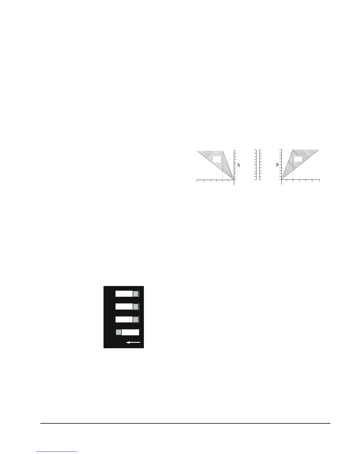
Integration Constant DIP Switch Settings
Depending on the application, the P352PN control can
be set to operate as a proportional-only control or as a
proportional plus integral control. Refer to sections
Proportional-Only Controls
and
Proportional Plus
Integral Controls
.
The control has three different integration constants to
choose from, which allow you to setup the control for
the optimum recovery rate for your application. Use the
Integration DIP switch shown in Figures 2 and 5, and
the guidelines below to set the control for
proportional-only or set to the integration constant rate
for proportional plus integral control.
•
OFF: Switch 1 On and all others Off
provide
proportional only operation. In open-loop
applications, (without feedback) select
proportional-only operation. (See Figure 5.)
•
Slow: Switch 2 On and all others Off
is the
slowest integration constant and is suitable for
most proportional plus integral applications.
Slow
is the recommended initial setting.
•
Medium: Switch 3 On and all others Off
provides a faster integration constant. If the rate of
system recovery to setpoint is sluggish when the
control is set to Slow, and the system has enough
capacity to drive the process to setpoint at a faster
rate, the Medium setting may be used.
•
Fast: Switch 4 On and all others Off
is the
fastest integration constant. This should be used
only in instances where the rate of change at the
transducer is extremely rapid and system capacity
is sufficient to compensate for rapid load changes.
43
21
O
N
FAST
MEDIUM
SLOW
OFF
(Proportional
Only)
Figure 5: DIP Switch for Setting Integration
Constant or Proportional Only Control
(Switch shown is set for Proportional Only Control)
Direct Acting or Reverse Acting Mode
In Direct Acting (DA) mode, the analog output signal
magnitude increases as the pressure rises. In Reverse
Acting (RA) mode, the analog output signal magnitude
increases as the pressure drops. (See Figure 5.)
Select the desired mode of operation by positioning the
two jumpers on the
J1
jumper block. Position the
jumpers vertically for Reverse Acting, or horizontally for
Direct Acting. (See Figure 2.)
The Reverse Acting/Direct Acting jumpers are installed
in the Reverse Acting position at the factory.
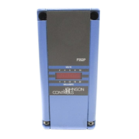
Note: Dashed areas show throttling range possibilities
from minimum to maximum.
VDC
Throttling Range
(psi)
Setpoint
10
0
0
RA
20
10
0
mA
Setpoint
Throttling Range
(psi)
10
0
0
VDC
DA
20
10
0
mA
(+)
(-)
10100
Reverse Acting Direct Acting
10
100
Figure 6: Reverse and Direct Acting Throttling
Ranges (Proportional Bands) Shown in
Proportional Only Mode
(Model Depicted has 10-100 psi Throttling Range)