6
Basic Controls—P352PN Electronic Proportional Plus Integral Pressure Controls for PSI Applications
D
imensions
DIN Rail Mounts
P352P
Mounting Slots
for No. 6 Screws
3/16 (4)
1/2 (13)
2-15/16
(75)
7/16 (11)
1-9/16
(40)
5 (127)
2-3/8 (61)
1-3/16
(31)
7/8 (22)
2-3/8 (61)
1/2 in. Tradesize
Conduit Opening
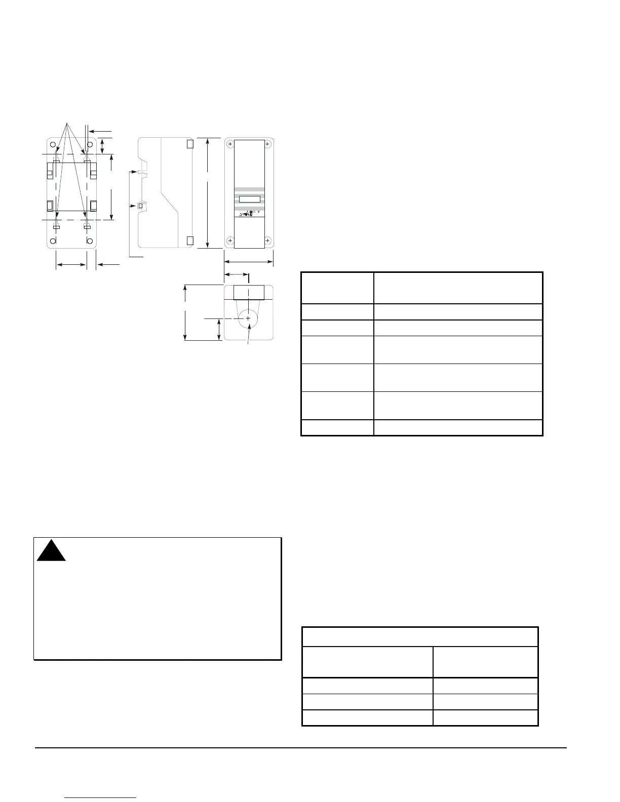
Figure 7: P352PN Control Dimensions, in. (mm)
I
nstallation and Wiring
The P352PN control is housed in a compact NEMA 1
plastic enclosure designed for standard 35 mm DIN rail
mounting. The control is not position sensitive but
should be mounted for convenient wiring and
adjustment. Four key-slot mounting holes on the back
of the control case are provided should surface
mounting be required.
Note: When mounting the P352PN control (or any
System 350 Module) to rigid conduit, attach
the hub to the conduit before securing the hub
to the control enclosure.
!
WARNING:
Risk of Electrical Shock.
This control, and any modules
connected to it, may have more
than one power supply.
Disconnect all power supplies
before making electrical
connections to avoid possible
electrical shock or equipment
damage.
•
All wiring must be installed to conform to the
National Electrical Code and local regulations. For
maximum electrical rating of control, see label
inside the control cover. Use copper conductors
only.
•
The P352PN control can output a variable signal
from 0 to10 VDC or 0 to 20 mA. Connections are
made to the terminal block located in the wiring
compartment at the bottom of the case.
•
Both the voltage and milliampere outputs can be
used at the same time, allowing the P352PN
control to drive two independent devices
simultaneously (off the same RA or DA ramp).
This feature may be used to drive different types of
motor actuators or variable speed drives.
Table 1: P352PN Control Wiring Terminal
Designations
Terminal
Designation
Terminal Description
V
0 to 10 VDC output signal
I
0 to 20 mA output signal
SN
0.5 to 4.5 VDC input signal from the
pressure transducer
VDC
5 VDC power supply to the
pressure transducer
C
Common for the pressure transducer
and output signals
24V
24 volts AC
Wiring the Transducer
The P352PN controls use a P399 Pressure
Transducer to generate the 0.5 to 4.5 VDC input
signal. The transducer is wired to the control at the
terminal block at the bottom of the circuit board. Refer
to Table 2 and Figure 2 for proper wiring configuration.
Connect the cable shield to C on the terminal block.
The maximum recommended length of 22 AWG
shielded transducer cable is 250 ft (76 m). Refer to the
P399 Electronic Pressure Transducer
Product/Technical Bulletin (LIT-125515)
for more
information about the pressure transducer.
Table 2: P399 Transducer Connections
Terminal and Wire Designations
P352PN Control
Terminals
Transducer Cable
SN
White
VDC
Red
C
Black