Basic Controls—P352PN Electronic Proportional Plus Integral Pressure Controls for PSI Applications
7
A
dd-on System 350 Modules
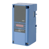
The D352 Digital Pressure Display Module, S352AA-2
Stage Module, and Y350R Power Module are designed
to connect together and plug into the P352PN control.
The power module connects to the control via a
connector on the control’s right side. The display
module and stage module connects to the right side of
the power module.
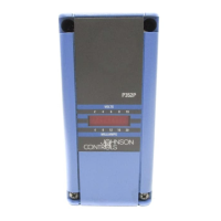
D352 Pressure Display Module
The D352 display module receives its power, pressure,
and setpoint information from the P352PN control. A
3-digit Liquid Crystal Display (LCD) gives continuous
read-out of the sensed pressure. Pushing the PRESS
FOR SETPOINT button on the display module displays
the P352PN control setpoint. Refer to
System 350
D350 Display Modules Product/Technical Bulletin,
LIT-930070
for more information.
Y350R Power Module
The Y350R power module provides a convenient
method of powering System 350 Modules from a
120 or 240 VAC power source. The power module
supplies power to all of the modules. Refer to
System 350 Y350R Power Module Product/Technical
Bulletin, LIT-930090
, for more information.
S352AA-2 ON/OFF Stage Module
The S352AA-2 stage module provides ON/OFF
pressure control based on the P5352PN control
setpoint and the stage module offset. Refer to
System 350 S350A Temperature, S351A Humidity,
and S352A Pressure Stage Modules
Product/Technical Bulletin, LIT-930080
, for more
information.
A
djustments
Use the following procedure to set up and adjust the
P352PN pressure control.
1. Remove its cover by loosening the four captive
cover screws.
2. Set the RA/DA jumper blocks to the desired mode.
Position the jumper blocks vertically for RA or
horizontally for DA mode. See
Reverse or Direct
Acting Mode
section and Figure 2.
3. Adjust the throttling range potentiometer to desired
setting. Rotate clockwise to increase the throttling
range. Refer to
Throttling Range (Proportional
Band)
section and Figure 2.
Note: If the P352PN control is to be used in
proportional plus integral mode, the initial
throttling range adjustment should not be set
below 30 psi for the P352PN-2 model or 60 psi
for the P352PN-3 and P352PN-4 models. A
narrow proportional band used in conjunction
with the integration may result in unstable
control.
4. If minimum output is required, set the minimum
output potentiometer to the desired position. The
10-segment LED bar graph or a voltmeter can be
used to read the minimum output. See
Minimum
Output Adjustment
section and Figure 2.
Note: Before setting the minimum output, verify
that the minimum output potentiometer is
set to zero (turned fully counterclockwise),
and that no LEDs are lit on the LED bar
graph.
For each 10% increase in output, the LED bar
graph will advance one LED segment
(only one bar is lit at anytime). In a milliampere
application, each bar equals 2 mA. In a voltage
application, each bar equals 1 VDC.
Example: To set the control for a minimum output
of 4 mA, slowly turn the minimum output
potentiometer clockwise until the second LED
segment just lights.
5. Adjust the P352PN control to the desired setpoint,
replace cover, and place the system in operation.
Table 3 gives the tolerances for setpoint readings
at mid scale and scale-end.
Note: The D352 Display Module is unaffected by
these tolerance shifts. Use the display module
to achieve the most accurate setpoint
selection.
Table 3: Setpoint Mid-scale and Scale-end
Tolerance Values
Control
Model
Mid-scale
Tolerance
Scale-end
Tolerance
P352PN-2
±1.5 psi ±2.5 psi
P352PN-3
±1.5 psi ±3.5 psi
P352PN-4
±3.5 psi ±8 psi
6. Make sure the operating system is stable before
setting the integration constant (if necessary).
Refer to the
Checkout Procedure
section and
Integration Constant DIP Switch Settings
when
setting the integration constant.