Basic Controls—P352PN Electronic Proportional Plus Integral Pressure Controls for PSI Applications
9
3. Check pressure transducer for proper output
signal voltage.
a. Measure and record the voltage between the
SEN
and the
COM
terminals on the control
terminal block.
V
o
= _______
b. At the same time observe and record the
pressure reading.
psi
T
= _______
c. The transducer output signal voltage (
V
o
)
increases proportionally to an increase in the
pressure at the transducer (
psi
T
). Use the
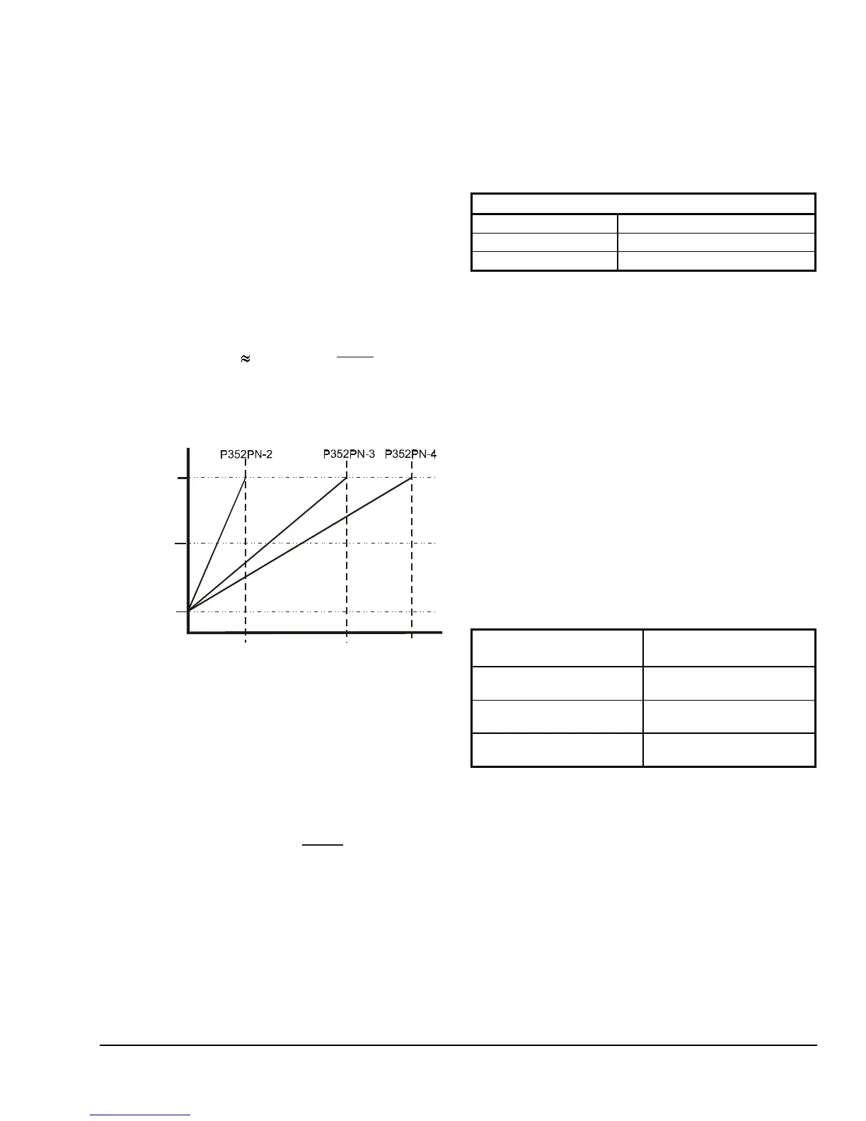
graph in Figure 8 to compare the measured
signal voltage to the measured pressure. Or
use the formula below to compare the voltage
and pressure values.
psi
T
(V - 0.5V) x
4V
P
max
o
psi
T
= Pressure measured at transducer
V
o
= Transducer output signal voltage (VDC)
P
max
= Transducer pressure range maximum
100 psi
500 psi
750 psi
(10%)
(90%)
(50%)
Pressure Range
Signal Output Voltage
(% of Supply VDC)
4.5 VDC
2.5 VDC
0.5 VDC
Control Model Number
Figure 8: Transducer Pressure vs.
Output Signal Voltage
Example:
The measured pressure at the gauge is
approximately 245 psi, the measured voltage
is 2.5 VDC (
V
o
), and the transducer’s rated
range is 0 to 500 psi (
P
max
). Use the formula
above to calculate the pressure you would
expect from the measured voltage.
(2.5V - 0.5V) x
4V
500
psi
= 250
psi
Since the measured pressure of 245 psi is
close to the pressure calculated from the
measured voltage (250 psi), the transducer
output voltage should be considered within the
desired range.
4. Check the P352PN control for proper operation.
Perform Steps 1-3 first.
a. Record the current setpoint, integration
constant, and throttling range in Table 4 below.
Table 4: Record of Current Settings
Current P352PN Control Settings
Setpoint
Integration Constant
Throttling Range
b. Set integration constant to OFF (proportional
only). See
Integration Constant
section.
c. Disconnect all power to the system and
control.
d. Disconnect the equipment from the control.
e. Reconnect power to the control.
f. Verify that the power supply and transducer
are connected properly.
g. Use an accurate gauge to take an independent
pressure reading at the transducer. (This
procedure requires a minimum of 30 psi static
pressure at the transducer.)
h. Set the P352PN control to Direct Acting mode.
Refer to Figure 2.
i. Adjust the throttling range potentiometer to
approximately 25 psi.
j. Observe the LED display while adjusting the
setpoint for each of the settings listed in
Table 5. If the display varies substantially from
these values, replace the control.
Table 5: Output at Select Setpoint Settings
Setpoint Setting
Approximate Output
Expected
At or Above Transducer
Reading
No LED bars lit
12 to 13 psi Below
Transducer Reading
4 or 5 LED bars lit
25 psi Below Transducer
Reading
All LED bars lit
k. Reconnect the equipment to the control. Reset
the control to the original settings (Table 4),
and reconnect power to the system.
l. Observe the system for a minimum of three
operating cycles. If the system still does not
perform properly, check application settings,
and replace the control if it does not operate
as expected for those settings.