2
Basic Controls—P352PN Electronic Proportional Plus Integral Pressure Controls for PSI Applications
A
pplication
A P352PN Series pressure control may be set as a
proportional-only control or as a proportional plus
integral control, to generate two standard analog
output signals (0 to 10 VDC and 4 to 20 mA).
The P352PN controls can be used as stand-alone
devices or in conjunction with plug-together power,
stage, and display modules.
A typical System 350
pressure control application
includes the following:
•
P352PN Pressure Control
•
Y350R Power Module (or 24 VAC transformer)
•
S352AA-2 Stage Module
•
D352AA-2 Digital Pressure Display Module
•
P399 Pressure Transducer
Typical P352PN pressure control applications include:
•
Condenser fan speed control
•
Damper positioning
•
Flow valve positioning
O
peration Overview
IMPORTANT: The P352PN controls are intended to
control equipment under normal
operating conditions. Where failure or
malfunction of the P352PN control
could lead to an abnormal operating
condition that could cause personal
injury or damage to the equipment or
other property, other devices (limit or
safety controls) or systems (alarm or
supervisory systems) intended to warn
of, or protect against, failure or
malfunction of the P352PN control
must be incorporated into and
maintained as part of the control
system.
The P352PN control operates on 24 VAC and provides
two analog output signals: 0 to 10 VDC and 0 to
20 mA. A 10-segment front panel LED bar graph
indicates percentage of output. Adjustable features
include:
•
Setpoint
•
Minimum output
•
Throttling range (proportional band)
•
Integration constant
•
Reverse acting or direct acting mode of operation
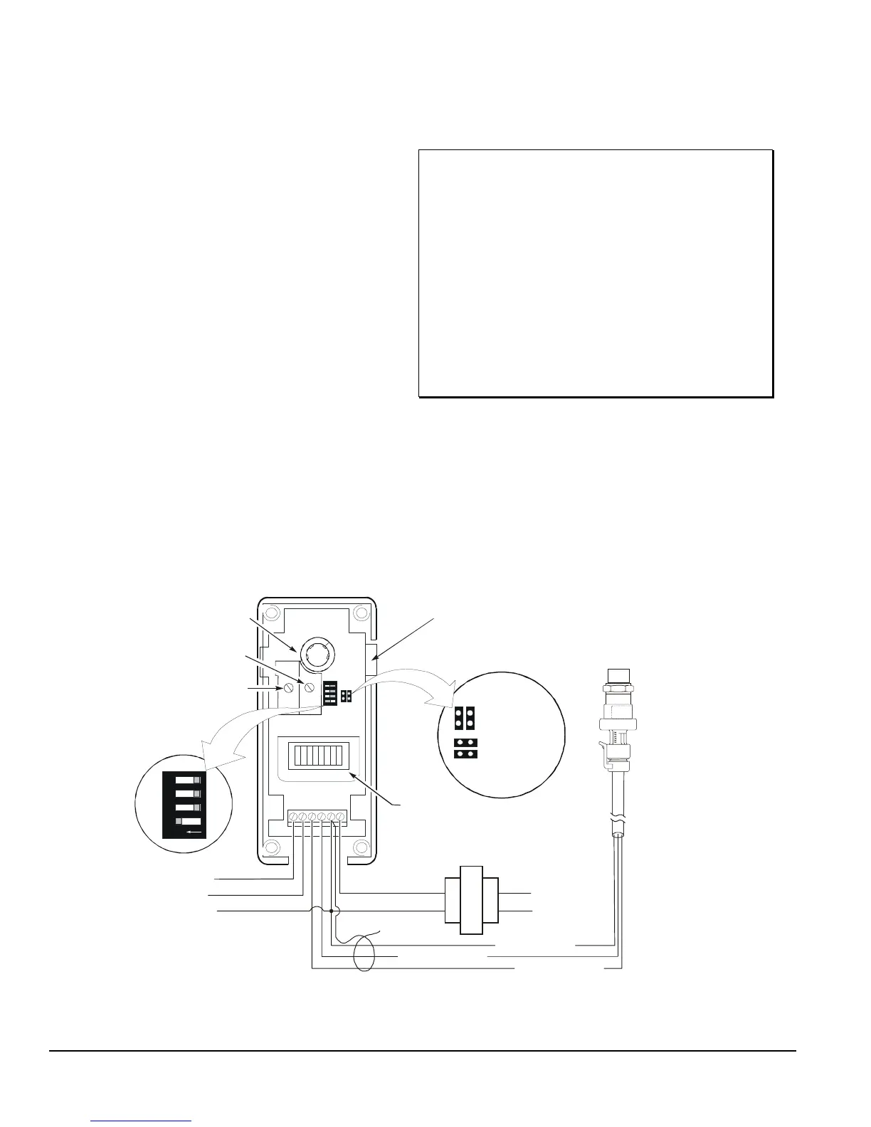
43
21
O
N
Module Connector
Reverse Acting
Direct Acting
J1 Jumper
Positions
LED Indicator
(Percent of Output)
0 to 10 VDC Output
0 to 20 mA Output
Integration
DIP Switch
V
I
C
24V
VDC
SN
THROT
RANGE
MI N
OUTPUT
PSI
Throttling Range
Potentiometer
Minimum Output
Potentiometer
Setpoint Potentiometer
Red wire to VDC
24 VAC Transformer
(If a Y350R Power Module
is not used)
White wire to SN
Black wire to C
24 VAC
Common for Analog
Outputs
120/240 VAC
WHA-P399
Wiring Harness
Connect Cable
Shield to C
P399
Transducer
Figure 2: Interior View and Typical Wiring of P352PN Control